The Adsitt Motor/Generator Project
The ELL Motor
Phase 1 - Theory of the Motor/Generator
I cannot claim full credit for this design. My father told me about this "steam motor" some 25 or 30 years ago, and at the time I didn't give it much thought. I'm sure there is an old patent on it for a steam motor, but I have not found it doing searches. However in searching for answers about utilizing the Lenz law to help "do work" and "not impede" it, I gave this some serious thought. I came to realize that this has extreme potential, and I have now been working on this for some time now. I now believe that OU is possible with this design, as well as extreme flexibility as other types of motors as well.
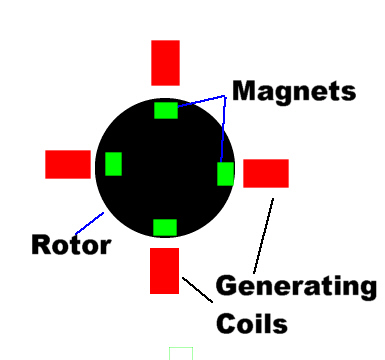
Consider the above drawing of a standard generator. As the magnets approach the coils, lenz law sets up and creates a magnetic field of the same polarity as the magnet and actually is trying to repel it away. The rotor is moving, but the coils are stationary. More and more force is needed to "push" the rotor over the coils. As the rotor passes TDC and moves away from the coil, Lenz sets up a magnetic field opposite the magnet and is trying to attract it back. This is why so much horsepower is needed in a conventional generator.
My thought in my design is that if you must have lenz law, then make it do some work for you.
Now lets consider the drawing below.
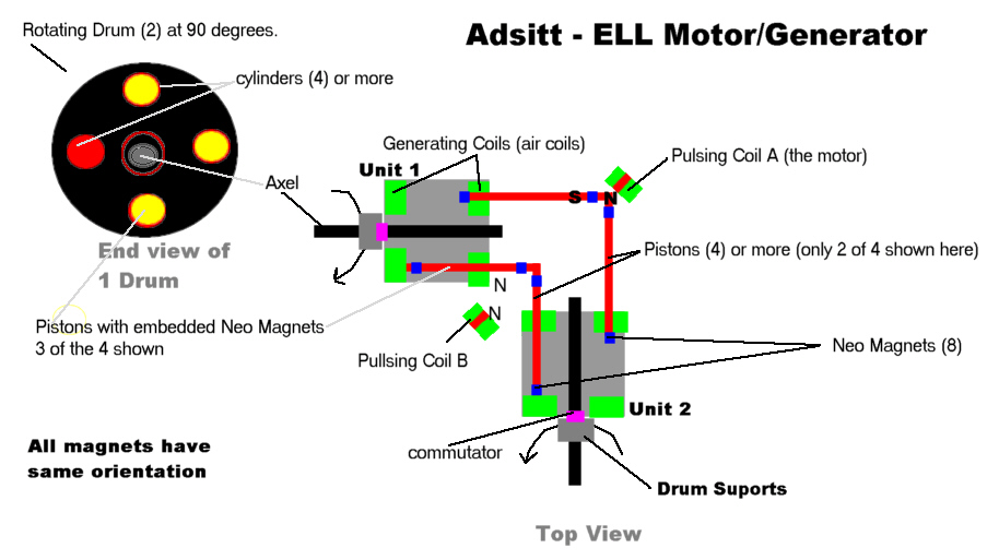
Now consider what is happing here as these two drums are tied together with common pistons. The pistons have Neo magnets embedded in them. As the drums rotate, the pistons are moving in and out. You can see from the drawing that as the piston moves away from one coil lenz sets up an attraction, but as the piston continues to move, it turns the rotor with it, as as it approaches the other coil, lenz sets up a field that repels the magnet, but as it further pushes , it turns the drum further. So in other words, even though you have lenz, you are able to transfer some of that energy into rotational power.
Now it doesn't quite just end here. If you look at pulsing coil B and the 2 generation coils it facing, you can see that as the drum turns, and the lenz increases in the generation coils, the generation coils build up a field and in the corner they want to repel each other as the magnet approaches TDC, causing the drums to spin away. Now as the piston starts to reverse direction and travel away from these 2 coils in the corner, the coils reverse polarity, and since the coil positions are still wanting to spin away, the coils still repel even though the polarity has reversed.
This should make for a virtually NO LOAD generator. Now all one has to do is add a couple of pulsing coils like that in the diagram - and that will be the motor. Pulsing Coil B further repels the coils in the corner, while pulsing coil A at the top repels the embedded magnets in the pistons.
Phase 2 - build a prototype of drums and pistons to prove concept.
Phase 2 is now complete as you will see in the photos and real player movie below. This seems to have many other potential uses in different configurations as well. As you can see that you really have 2 independent units that are slaved together. You possible could configure this concept as in the chart below.
| Unit 1 | Unit 2 |
| Electric Motor | Electric Motor |
| Electric Motor | Generator |
| Electric Motor/Generator | Electric Motor/Generator |
| Electric Motor | Air/Gas Compressor |
| Electric Motor | 2-stroke gasoline motor |
| Gasoline motor | Gas Compressor |
| Diesel Motor | Diesel Motor |
| Diesel Motor | Gas Motor |
| Diesel Motor | Generator |
| Air Motor | Generator |
| Air Motor | Air Motor |
| Steam Engine | Steam Engine |
|
Just some of the many possibilities with the right engineering. |
|
|
|
|
|
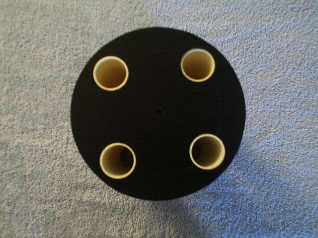
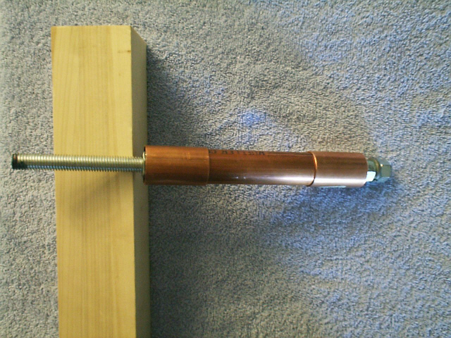
Below are the photos of "proof of concept" for slaving the drums and pistons with embedded neo magnets. There are other coil and magnet interactions not discussed yet, left for other Phase testing.
Unlike conventional generators, in that when you draw more power from the coils the generator slows down because of the increase in the lenz law, in this design, I believe then when you draw more power (increase the lenz), it pushes (or pulls) on the drums harder, INCREASING the drums RPM. You really have to think about this. No matter what the force of lenz - when the piston pushes towards the coil, the Drum MUST turn - and in consequence the pistons MUST go closer to the coil further increasing lenz but pushing again at the coil, the drum MUST turn and again the piston MUST draw closer until TDC. The drums them selves act as fly wheels - although you could mount a fly wheel on the motor mount end. Also the motor mount end of the drums could be geared together to send power to something else via a transmission for example.
The efficiency would be increased with larger diameter drums and more pistons.
Where coils are wound over the cylinders inside the drums, also inside the drums must have full wave bridges for each coils output since the AC output of the coils are different phases.
Click photo for larger image
 |
 |
 |
 |
 |
| Assemble Ell Motor | Top View | End view - Drum | Side view - Drum | magnet inside piston arms |
 |
 |
|||
| support column and center bearing\commutator support | Commutator parts |