24,500 Pulses (3120 RPM) Pulse Motor with 8" Rotor

See the real player movie of this motor.
![]() or Main
Menu
or Main
Menu
As built by Don Adsitt
Build at your own risk!
The SCHEMATIC DIAGRAM is HERE.
|
24,500 Pulses (3120 RPM) Pulse Motor with 8" Rotor |
|
|
|
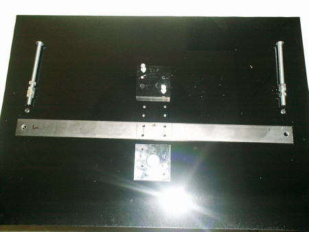
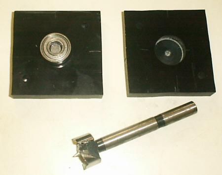
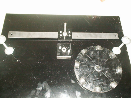
| Made a base 16" X 20", Top Bearing support bar is 1-1/4" by 20" X 1/8" steel,. the bolts are 5/16" X 5", and the bearing support blocks are 2-1/2" X 2-1/2" blocks made from 1/2" thick acrylic plastic. (same as base material.) | The bearings are roller-blade bearings with 3/8" hole. Cut about 5" from a 3/8" steel rod (can buy at Home Depot or Lowell's) for the axel. Drill hole with a 3/4" forsner bit or what ever size you use for your bearings. The bearings need to fit very tight in the holes. I put a slight amount of epoxy on the outside of the bearing and glued them into the holes. |
|
|
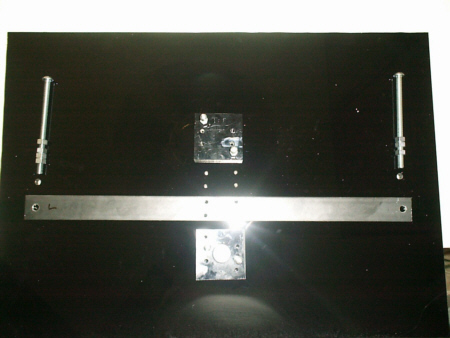
| For exact alignment of the bearings cut a short 1/2" piece of shaft and connect the upper and lower bearings and blocks together, then drill holes through both pieces into the steel bar. Then drill holes again same way but into the base so the bottom bearing block is mounted to the base in the center of the base. Then drill holes at the end of the steel bars into the base for exact position. (or use what ever method you want just so the top and bottom bearings are exactly aligned.) | Here it is bolted together to check alignment. You can fasten the bearing blocks to the base and steel support with 1/8" X 3/4" bolts and nuts. |
|
|
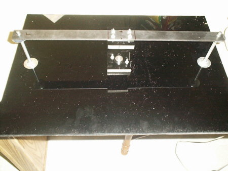
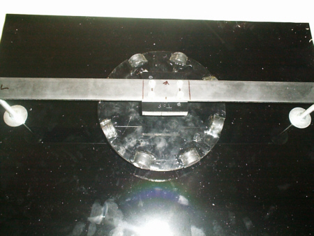
| The rotor is made from 1/2" thick acrylic plastic, cut into a 8" circle. A hole is drilled in the center to match the shaft size (3/8" in this case) You must use a drill press to drill this hole as it must be perfectly in the center and straight up and down. I marked the exact center before cutting the circle, then went back and drilled the hole. | The rotor has 1" slots cut into it in 8 equal divisions. These slots are cut to fit (4) 1" disc magnets glued together into one slot. Use 5 minute epoxy for all your gluing and don't spare the glue. Cover the entire magnets with glue. You don't want these magnets flying out when the rotor turns at thousands of RPM. Assemble the rotor between the bearing blocks as shown and mount the upper support. Adjust for square. The shaft should be tight enough that you need to use a small hammer to drive the shaft into the rotor. Adjust where the rotor is horizontally to be in alignment with the coils. (next picture. |
|
|
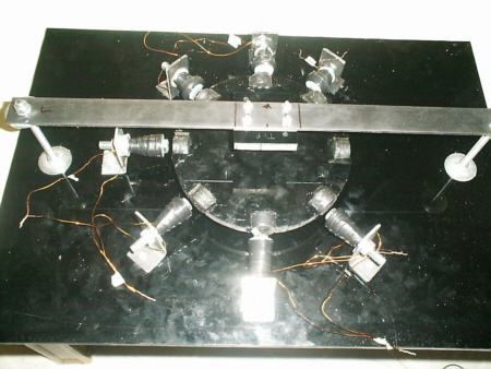
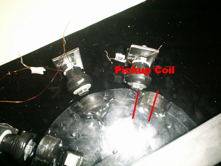
| Next mount your coils on L-Brackets -either make them yourself as I did from the left over steel bar, or use L-brackets from the store. Coils should be about 3/8" away from the coils. Test each coil separately to find out with the power on, which direction is north - or so that they repel the rotor magnet. Each pair of coils are wired in parallel , one lead goes to the collector of the transistor, the other directly to the positive side of the battery. | This motor uses only one pickup coil. Notice that when the motor spins clockwise, The coil is placed behind the passing magnet in order to maximize the pulse position. When you first start the motor, don't fasten this coil down. Move the coil left or right as the motor starts to find the best position. Watching an amp meter helps. You want this coil just a hair away from the rotors outer edge. One side of the pickup coil goes to all transistor bases, and the other side to ground. |
|
|
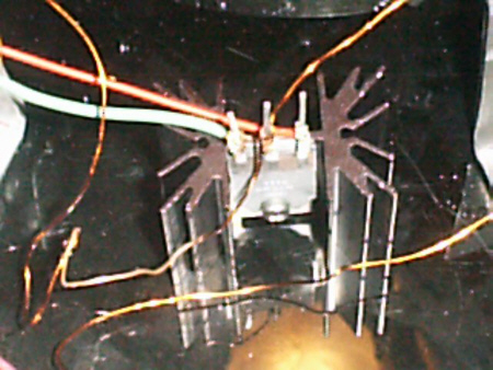
| If you use heat sinks mount them between the coils. Each coil will draw just over 1 amp DC and at about 2-3 amps the transistor gets very hot. This is normal, but a heat sink is needed. Although 1 transistor will easily run 3 or 4 coils, I have two coils wired to one transistor. The bases of all transistors are connected together which is connected to one side of the pickup coil. The other side of the pickup coil goes to ground. | Here all the transistors (3) and heat sinks are wired. [I have added extra heat sinks and transistors in this photo for future test.] Use 1 transistor for each pair of coils. No transistor for the pickup coil. |
|
This motor runs at 3120 RPM as viewed on a oscilloscope. The pulse
time division is 1ms, reading DC with channel one, and using a 5 volt
scale. The time from pulse to pulse should show 2.4 ms or 416HZ, divided by 8
magnets = 52, times 60
seconds = 3120 RPM. Your motor may run faster or slower depending
on how carefully you built it and the coils you used. See
How to make these coils for duplication of this motor.
See the real player movie of this motor. |
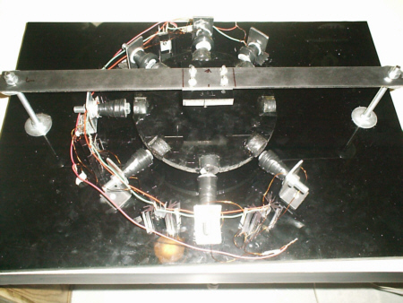
| Here the motor is complete. Ready to run. Use caution as you adjust your pickup coil for the first time. The rotor speed is controlled in several ways. If the drive coils are further away then 3/8" it will run slower. If the pickup coil is further way it will run slower, and if the pickup coils position is left or right of it's optimum position it will run slower. Make sure the drive coils and magnets are centered as you position the coils. Once you've found the right place for the pickup coil, stop the motor and mount it into place. Enjoy! |
|