Block Diagrams and Parts List for;
Tilley Building Power Systemby Jerry Decker for KeelyNet
& Tilley Electric Vehicles

Proposed Block Diagram for Tilley Building Power System
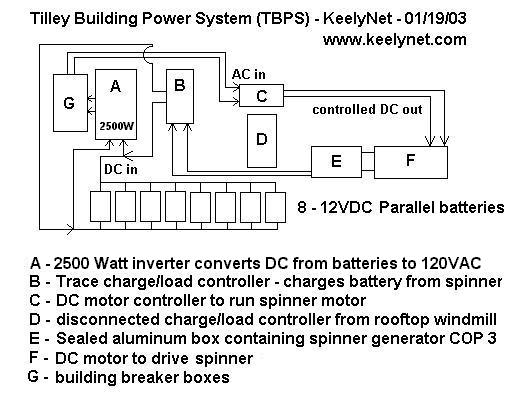
The following diagrams are purely the result of my own imagination and ideas as to how I think the Tilley claims could work. They are purely speculation and probably have errors I missed or dreamed up. Your comments and opinions can be sent to the email address above. Thanks! John Bedini thinks it is one of his gravity fed motors where the secret was released in 1984 and which, like the Tilley motor simply required a drive motor to produce the excess power. I respect John's opinion and he might well be right, but before he came forward with this, I was thinking about Carl and some things he told us. No doubt some were misdirection and because it is a business, I can understand why Carl and his associates would do this. It was quite an amazing thing to be allowed the open access they freely gave us, which to my view, gives them a certain degree of credibility as to the CERTAINTY that what they had isn't a scam. But only time will tell with this. It seems to me that our questions indicated Carl knew nothing about Tesla or any other researchers working with electrical generators. Instead, I got the impression based on his description that he had designed and installed off-the-shelf wind and solar power systems when he said he kept 'running out of daylight' to keep the solar cells generating. That is when he got the idea for the spinner. It strikes me that he would have kept abreast of anything new that would be of use in his business including generators. I have long been fascinated by neodymium and rare earth magnets because of their incredible strength in such a small package so decided to see if I could find anything that he might have stumbled on and tested successfully. Using that as my query, I looked for anything unique or novel about a neodymium based generator and found just such a thing at hydrogenappliances.com where something called a MANTA generator was claimed to produce 12VDC @ 35amps with just one turn of the shaft by hand. Now 12V X 35A = 420Watts. Granted its only a burst of energy but if attached to a drive such as a motor, it just might put out more than what it took to run it by using super strong neodymium magnets. I posted this to the KeelyNet Interact discussion list and received not one single response saying I was full of baloney. Usually someone would tear into something like this and at least correct my erroneous thinking. The closest thing was the observation that the torque necessary to spin the generator UNDER LOAD would be significantly higher than WITHOUT A LOAD. I didn't bring that up in the original post because so many have had the chance to play with the old Army field telephone generators, where the handle spins freely with no load but is very hard to turn with a load applied. But it is a valid point that must be stated. However, with a generator such as the MANTA connected to a charge controller that fed a battery network, I think the load might require less torque than we think, thus allowing excess energy to be produced and fed into the batteries. The purpose of this page is to provide simplified block diagrams of both the Tilley Building Power System and the Tilley Electric Vehicle. This in no way is making the claim that it is correct, just information correlated and gleaned from my notes and the many on the net who have shared their observations. Both systems appear to use off the shelf components for the ENTIRE system except for whatever is in the mystery spinner box. Here is my block diagram of the Tilley Building Supply System based on the photos, video and information I have gathered to date; The simple logic of it as I can determine;
- 1) - Parallel 8 battery network provides 12VDC to the inverter for 120VAC output
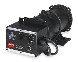
- 2) - 120VAC feeds the DC motor controller from Grainger
- 3) - DC from motor controller adjusts speed of spinner
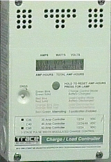
- 4) - spinner output feeds the charge/load controller
- 5) - charge/load controller adjusts power in to recharge the battery network
- 6) - battery network is kept 'topped off' to optimum 12VDC or so by controller
- 7) - inverter provides additional AC through breakers for other building loads
The TRACE charge/load controller is a C-40 model with digital display, rated as charging/load current at 40 amps DC and costs about $160 with meter. I did get a closeup of the TRACE 2.5kw inverter which I first posted as 25kw based on what Carl said, until I was corrected by Craig Paterson of Australia. The spinner is of course the key to the entire thing with the output as claimed by Carl to be three times more out than what it takes to run the motor (a COP of 3 - coefficient of performance used to rate efficiency). Other pages in this seven part series suggest possibilities as to what the spinner might be. I have not included some of the more outrageous suggestions, including electrostatics, scalars, etc.. Unfortunately, the visit to the workshop was completely unplanned so we didn't get to measure or test anything, not wanting to strain our special invitation out of all the folks who attended the demonstration. Parts list for the building power system as far as I can make out;
- A - 2.5kw Inverter (converts 12VDC to 120VAC for building power)
Model U2512SB RV/Marine Series - $1495.00- B - TRACE brand C-40 Charge/Load Controller (40 amps) - $160.00
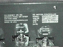
- C - GRAINGER 1F800 - DC controller/motor that drives spinner
1/2hp / 1725RPM / 56C / 115 input volts / 90 volts / 5.40 amps - $497.25
HP @ 1725 RPM = 0.500 - Max Torque @ all speeds (inch-pounds) 16.2
from www.grainger.com
- D - same Charge/Load Controller as B above but disconnected
- E - Spinner with COP 3 - proprietary device inside shielded box
Tilley claims spinner is $25 WalMart item which is then 'modified'- F - Grainger motor as part of controller/motor item C above
- G - 1000 Amp/DC Safety Distribution Center - TRACE PC250
PV Charge Controller

Proposed Block Diagram for the Tilley Electric Vehicle
The following diagram is my idea of how Tilley adapted the building power system to run an electric car. Please note the need to;
1) - control the 144vdc to the 90-144vdc motor 2) - use a DC/DC converter rated at 144vdc to 12vdc for the car electrical system 3) - convert the proposed 12vdc from the spinner through the charge/load controller into a differently rated DC/DC converter for the 12vdc to be changed to 144vdc - this is to recharge the 12 battery Series network
(12 batteries X 12vdc = 144vdc) The logic flow for the electric car system to me is;
A parts description list follows;
- 1 - 144vdc from the series battery bus is fed to the motor using a DCP motor controller
- 2 - 144vdc from the series battery bus is fed to a DC/DC controller to produce the 12vdc needed to run the vehicle electric system, such as lights, etc.
- 3 - 1/2 of the 90vdc dual shaft motor drives the vehicle transmission for propulsion
- 4 - the other 1/2 of the dual shaft motor runs the spinner which like the building power system probably puts out something like the COP 3 (three times more out than in)
- 5 - the spinner power feeds into a TRACE charge/load controller which provides stable DC
- 6 - the 12vdc from the charge/load controller feeds a DC/DC converter which converts it up to 144vdc which is added back to the battery bus to recharge the battery network
- A - twelve 12vdc WalMart FLEET batteries in series for 144vdc
Model 31-5T / Cranking Amps - 1190 / Cold Cranking Amps - 1000
- B - DC Motor controller which is the Raptor 600 model as posted at;
http://www.dcpowersystems.com/r600fly.htm Input Voltage Range: 48 - 156 VDC Nominal (40 - 180 VDC MAX)
Output Current (Battery): 600A max, 300A sustained @ 40C, derate 40A per 10C rise above 40C
Freewheel current (Motor): 900A max, 350A sustained @ 40C
Switching Frequency: 18Khz
Rev Limit: 4000, 4500, 5500, 6500 RPM
Shift Blanking Input: 50 or 100mS one-shot PWM dropout
Contactor control: Switches 4A rated 12V coil. Uses vehicle 12V
Operating temperature: -20C ~ +75C
Weight: 18 lb.
Dimensions: 6.75 x 9 x 12 (HxWxL")
Throttle Sensor, Remote Display and Tach Sensor Included
$1595 + Tax & Shipping Made In USA- C - 100HP / 90vdc dual shaft motor
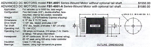 Large Motor #FB1-4001 Cost - $1,623.00 / Shipping - $95.00
Test Data @ 144 V Input
Length
Diameter
Weight
Input Voltage
Efficiency
15.70" 9.1" 143.0 lbs. 96-144 V 90.0% Peak Horsepower 100.00 Price list page with meters, gauges, motors, mounts, etc.; Electric Auto Website
Time On
Volts
Amps
RPM
HP
KW
5 min. 134.0 320 4200 48.80 36.80 1 hr. 138.0 185 5700 30.40 22.90 Continuous 139.0 170 6000 28.50 21.50
- D - probably use extant car transmission, only requires a motor coupling
- E - Tilleys spinner device with COP 3, might be slightly different from building power supply spinner
- F - probably TRACE C-40 charge/load controller though could be larger due to more batteries, maybe a C-60
- G - probably a DCP brand DC/DC converter for 12vdc changed to 144vdc
- H - definitely a DCP brand DC/DC converter for 144vdc changed to 12vdc

- I - 12vdc bus for automotive electrical system
I think the system to try to duplicate would be the building power system but using a more reasonable sized inverter scheme. In fact, because I am a big fan of 'distributed sources' such as 'perpetual batteries', I would rather use an inverter for each breaker, roughly 20amps at 120vac which comes to 2400Watts. Not only are they cheaper but more widely available and efficient to replace should they fail. Remember CONSOLES and how you used to have basically one built-in amplifier which simply accepted input from various console peripherals (TV, FM tuner, CD player, etc.) so if the amp goes out, because everything is built into one big cabinet, you lose use of it all until you get that amp fixed. As opposed to modern modular systems where you can swap out just the amplifier. In this case, I'd rather replace one inverter at a time that fed just one breaker than some monster $15,000 to $20,000 unit!! So, for a home power system or at least one we can test, I think we would need; 1 - $1200.00 - a special generator as detailed on page 7 of this series and what I think is the 'secret' of the SpinnerThat comes to $3430.00 which I would round out to $5000.00 to actually buy the equipment, cover extraneous costs and run the test with various loads to see if the thing really does keep the batteries recharged without running down.
2 - $500.00 - a DC controller/motor as from Grainger
3 - $650.00 - a bank of 8 batteries
4 - $180.00 - a charge/load controller
5 - $900.00 - approximate total for two 2400 watt inverters
1) - The Trip
4) - Block diagrams w/parts listings
2) - The Tilley Building Power System
5) - Bedini Gravity Field Generator
3) - The Tilley Electric Vehicle
6) - The Wilson Machine
7) - The Manta Generator
Contact the Tilley Foundation for updates and further information
If you found this file useful or interesting, please consider a donation or a purchase to help keep KeelyNet online and providing free information. Thanks!