By John V. Milewski
August June 2001
PROCEDURE:
A. Vortex chamber sub-assembly
Refer to parts list at the end for the list number and description of all parts.
1. Take the 1 ½ slip coupling (Part 1) and grind down the ridge in the center.B. Drilling of side port hole porthole in vortex chamber sub-assembly.
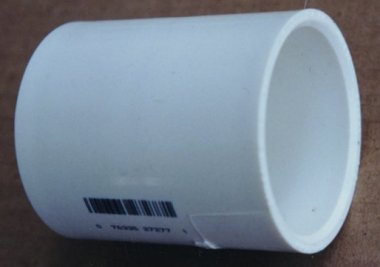
1 ½" slip coupling
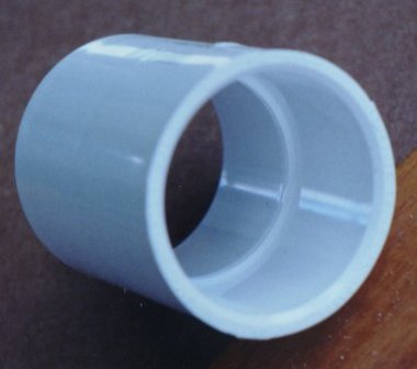
View of ridge in center of coupling
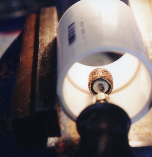
Grinding off ridge
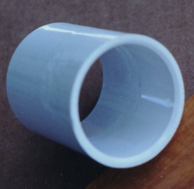
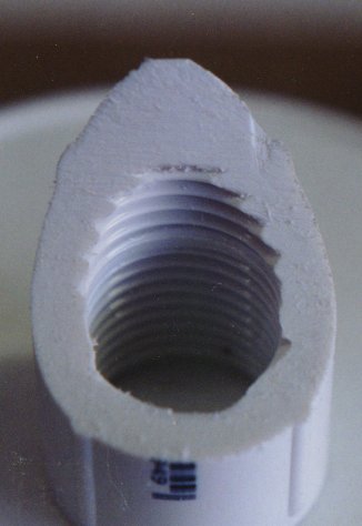
Coupling with ridge ground off2. Take two 1 ½ slip to ½ threaded bushing (Parts 2) and hammer or press into the 1 ½ coupler (Part 1). Before pressing, coat all contact side of Parts 2 and only the lead in surface of Part 1 with PVC solvent cement (Part 3).
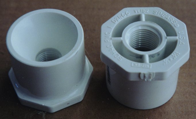
1 ½" Slip to ½" threaded bushing
Vortex chamber parts
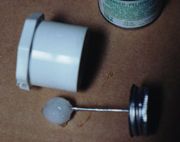
Ready to put solvent on fitting
Assembled vortex chamberAfter assembly, reach inside with tissue on small finger and wipe off any excess cement that might have squeezed out at the contact joint between the two bushings.
3. File the eight corner edges on Part 2 on one side of the vortex chamber assembly to allow the magnet (Part 12) to fit over it on to the assembly.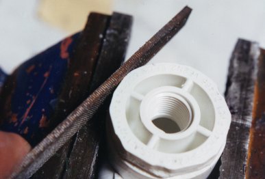
Filing corners of fitting
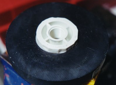
Magnet around trap body
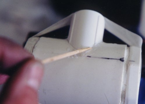
1. Carefully measure the position where you calculate the contact center will be for the two slip bushing inside of the coupling and mark this on the outside to locate the drilling position for the input nozzle. Since, in some cases, the length of the coupling (Part 1) is shorter then the two lengths of the slip bushings (Parts 2), you cannot use the center of the coupling as the place to drill. (Photo 11)C. Cutting and assembly of input port for injection nozzle.2. Mount the vortex chamber assembly in a vice or fixture to hold it in a vertical position. In this vertical position measure in 5/16 of an inch from the straight surfaces of one of the octagonal faces of the Part 2 and draw a cord line from one edge to the other. From one outside edge of this line, draw a line down to the drilling position marked earlier. Insert a 1/8 inch drill bit (Tool 1) in the electric drill (Tool 2) and position it perpendicular to the side and parallel to the top to the location just marked. This is where you start drilling in to form the input hole for the injector nozzle. Note! it is difficult to get the drill bit started by coming in at such a side angle so start the drilling perpendicular to the surface for the first 1/16 of an inch and then reposition, while the drill is still running, to the correct position as shown in the pictures.
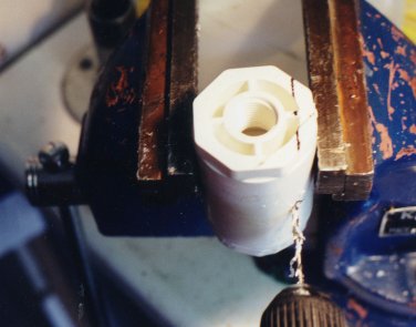
Drilling input hole
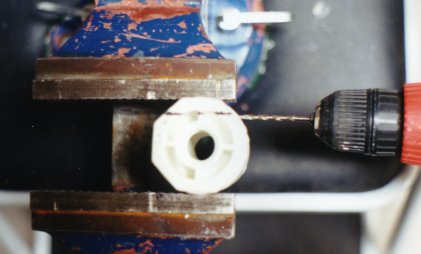
Drilling input hole (from above)3. After drilling through to the center, clean the hole by hand with the drill bit to remove any residual edges or burrs.
4. Next bore out or enlarge the hole just made for about 1/8 of an inch using a ¼ inch drill bit (Tool 3). This is the size hole needed to receive the nose of the sweeper nozzle to be inserted later. Be careful as the drill bit may want to go in all the way so hold it back to only 1/8 inch countersink.
Input hole showing countersink for sweeper nozzle
1. Take two of Parts 4(1/2X4 PVC threaded nipple) and thread into Part 5 (1/2 female to female threaded coupling). Lay this assembly on a board and hold it in place with nails.
Ready to cut input coupling2. Put the 2 ¼ inch hole saw (Tool 4) with a ¼ inch pilot bit inside into the electric drill. The pilot bit should be long enough to extend at least 2 inches beyond the end of the hole saw.
Hole saw in drill3. Start the drilling with the ¼ inch drill bit as close as possible to the contact position of the pipe nipple and the treaded coupler. Use the position of the drill in the wooden frame to keep the position of the hole saw steady when cutting the threaded coupler.
Looking straight down on threaded input coupler
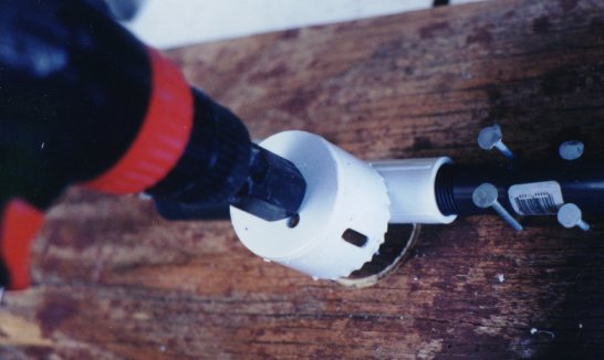
Ready to cut threaded input coupler
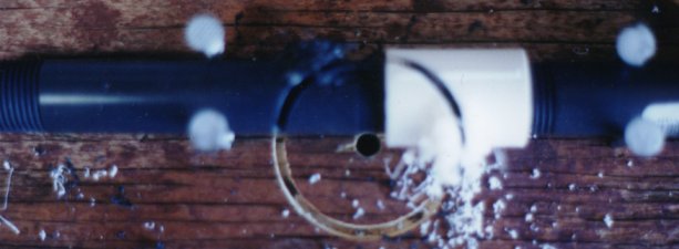
Half way through the threaded input coupler4. Once you start drilling and sawing continue as smoothly and as uniformly as possible to prevent gouging and formation of ridges in the cut bushing so less sanding will be required when finished. When sanding use the outside of the slip coupling (vortex chamber assembly) as a guide for the sandpaper to obtain the correct curve on the matching surface to be bonded.
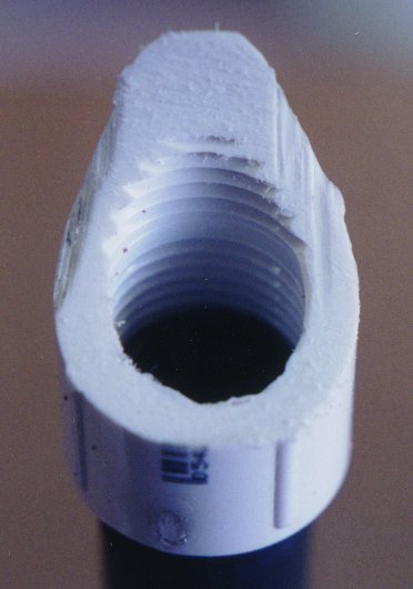
Rough inlet port after hole sawing
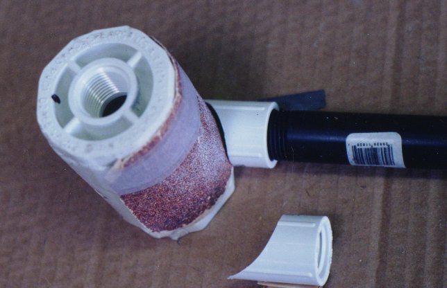
Sanding inlet port against vortex chamber assembly
Inlet port after sanding
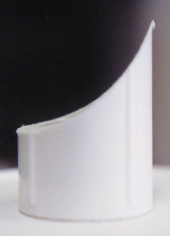
Side view of inlet port after sanding5. After sanding the surface of Part 5 smooth, place the vortex chamber assembly (Parts 1 and 2) in a vise to position it for bonding.
6. Apply a generous supply of the PVC solvent cement (Part 3) to both contacting surfaces. Wait a few seconds to allow the cement to soften and bond to the plastic parts and then position the curve cut threaded coupler centered over the hole just drilled in the vortex chamber assembly and hold it in place with tape as shown below:
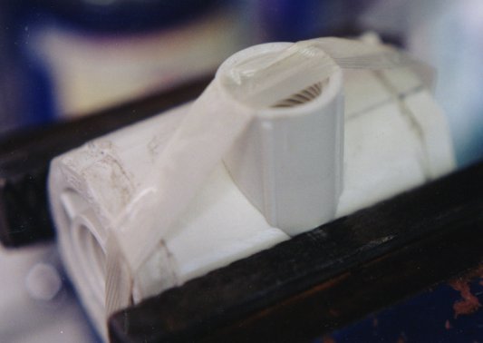
Inlet port being solvent welded to vortex chamber assembly7. Apply extra solvent cement to any gaps in the contact area and/or wipe off any large excess.
Applying extra solvent cement to fill gaps
D. Addition of nozzle into input port.
1. Take the plastic sweeper nozzle (Part 6) and place it in a vice and cut off the nose portion.

Plastic sweeper nozzle
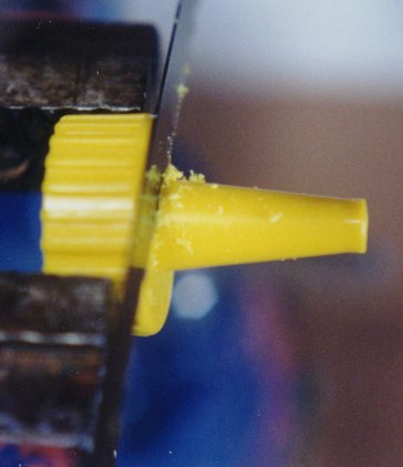
Cutting off nose of plastic sweeper nozzle2. Sand off the rough edges and taper the input edge with a razor knife to permit a smoother in flow of the water.
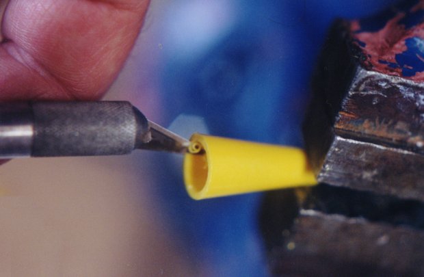
Tapering input edge of plastic sweeper nozzle3. Glue the nozzle into the hole prepared in the vortex chamber assembly.
4. Cover the threads on the ½" male threaded pipe to female hose connector (Part 7) with Teflon tape and screw it into place.
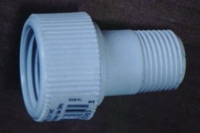
½" male threaded pipe to female hose connector
Completed vortex chamber and inlet port assembly5. When the assembly is complete look down the attachment just made through the nozzle to see that the hole is still clear. Remove any excess cement if necessary.
E. Addition of m-state exit port and main water outlet.
Look into inlet port to be sure the hole is clear of solvent cement
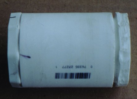
1. Cut two pieces of the 3/8" braided poly rope (Part 8) 12 inches long. Obtain a piece of wire (Part 9) twelve inches long, copper or steel, what ever. Next get the 1/2 X 4 PVC pipe (Part 4) and ream out one end with a razor knife to about 1/8 to eliminate the sharp edge and make the end like a small funnel.Now take the pipe out of the vice and take off the threaded coupler to expose the poly rope coming through the pipe. Cut the wire on one end as close as possible to the poly loop and pull the wire out. Grab the tail end of the poly rope and pull it back till the loop is flush with the end of the pipe.
Ready to pull poly rope through the 4" pipe nipple2. Screw this end into a threaded coupler (Part 5) and put this assembly into a vice or holding fixture. Now take the two pieces of braided poly rope and bend them in half. At this bend put the wire through the loop and twist the wire to hold the rope together. Next push the wire through the 4 inch pipe nipple and on through the threaded coupler. Bend the poly rope and squeeze it so it can be pulled through the pipe into the threaded coupler.
Pulling the braided poly rope through the pipe nipple and coupler
Braided poly rope is far enough in3. Using pliers, pull the poly rope through the pipe just enough to have the loop of the poly rope projecting about ¼ of an inch beyond the end of the pipe.
Ready to remove the pull wire from the poly rope loop
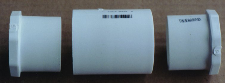
For the purposes of this document we will describe the method illustrated in the center above. Put the threaded coupler back on the pipe nipple opposite the end with the folded end of the poly rope.
Using the vise to pull the poly rope back till it is flush4. Examine the end of the poly rope that is still projecting out of the end of the pipe. The rough end of the poly rope is now cut off flush. At this point there are several ways you can finish the top end of the m-state exit port depending on the availability of various fittings at your hardware store. These ways are illustrated below.
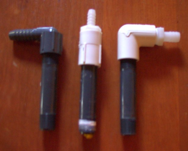
Different ways of finishing off the top end of the m-state exit port
5. Take the 1/2 "threaded nylon to ¼ tubing barb (Part 10) and ream or carve out the inside on the ½ " threaded end as shown below.Then screw this into the open end of part 5 that is attached to the 4" nipple with the poly braid inside. Now screw this outlet assembly into the vortex assembly, as shown below, on the end opposite that which will hold the magnet structure assembly. Next take the ½" male to 5/8" hose barb (Part 11) and screw this in to the other end of the vortex assembly. This is the waster water outlet. Both outlets are shown below.
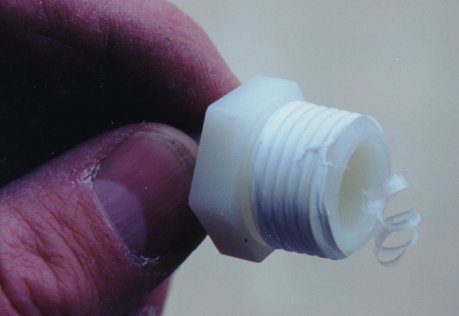
Nylon tubing barb adapter showing tapered inside cut
F. Magnet structure assembly.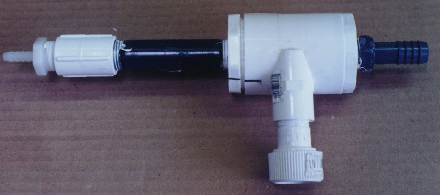
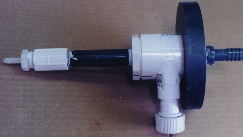
Vortex chamber assembly with m-state outlet to the left and waste water outlet to the right
1. The magnetic assembly consists of four parts. Two ring magnets (Part 12), one 1" floor flange (Part 13) and one 1" X 2" galvanized pipe nipple (Part 14 ).G. Leg assembly2. Assemble the pipe nipple into the floor flange.
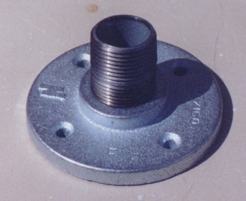
Pipe nipple screwed into floor flange3. Now slip the magnets over the end of the vortex assembly that it fits on. Then add the floor flange assembly.
Vortex chamber assembly with first of the two magnets on it
1. The leg assembly consists of ten parts. One 8" X 8" X ¼" acrylic sheet (Part 15), Three end caps for ½" PVC pipe (Part 16) and three 1"X1/4"-20 stainless bolts and nuts (Part 17) and three pieces of ½: PVC pipe cut to 7" length (Part 18).H. Options2. Take the acrylic sheet (Part 15) and draw a line from corner to corner. This will locate the center. Draw a 3 1/4" radius circle. Mark off three equally spaced spots on this circle in order to locate the position for the legs. The first spot is at top center and the other two at 5 ½" distance from the point where it intersects the circle.
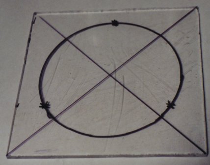
Hole locations laid out on acrylic sheet3. Drill a ¼ "hole at each of these marked positions. Next drill a hole in the center with the hole saw (Tool 4) used earlier.
4. Next take the three end caps and sand the ends to form a flat on the end.
5. Drill a ¼ " hole in the ends of each cap.
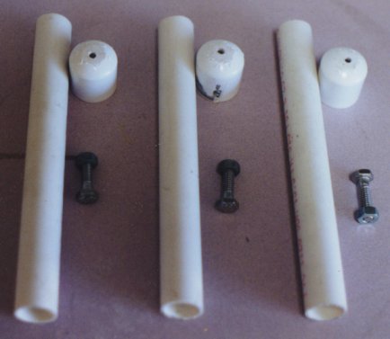
Leg parts with holes in end caps6. Put the screws in from the bottom of the plastic sheet and place the end caps on the screws. Screw on the nut and tighten fully.
7. Next put the PVC pipes into the caps and press down firmly. This is the leg stand for the vortex assembly.
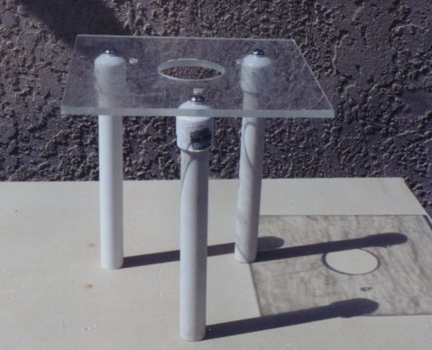
Completed leg assembly8. Put the vortex assembly with magnets and flange in place in the leg assembly.
9. Now add the 18 inch length of ¼" clear plastic tubing (Part 19). The unit is now complete.
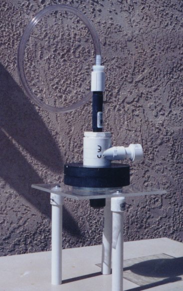
Completed Tiny Trap
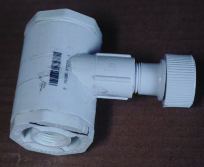
1. A plastic quick disconnect (Part 20) for the input nozzle.2. A water filter (Omni, Culligan or equivalent) is preferred if city water is chlorinated or if your water source contains sediment.
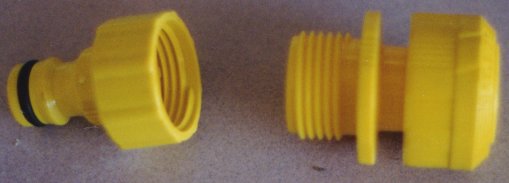
Quick disconnect coupler
|
|
|
|
|
1 ½" Slip coupling |
|
|
1 ½" Slip to ½" threaded bushing |
|
|
PVC Cement |
|
|
½" X 4" PVC nipple |
|
|
½" female-to-female threaded coupler |
|
|
Plastic sweeper nozzle |
|
|
½" male threaded pipe to female hose connector |
|
|
½" braided poly rope |
|
|
12 inch long wire |
|
|
½" threaded Nylon to ¼" tubing barb |
|
|
½" male pipe to 5/8" hose barb |
|
|
Ring magnet (2.25 ID X 5.375 OD X 0.75 thick) |
|
|
1" Floor flange (US made for smooth bottom surface) |
|
|
1" X 2" galvanized pipe nipple |
|
|
8" X 8" X 1/4" clear acrylic sheet |
|
|
Three ½" slip PVC end caps |
|
|
3 - 1" ¼ -20 stainless bolts with nuts (stainless preferred) |
|
|
3 - 7" pieces of ½" PVC pipe |
|
|
1/8" clear plastic tubing 18" long |
|
|
Plastic hose quick disconnect |
Estimated cost of all parts with magnets:
$40 to $45
| TOOL LIST |
|
| 1. 1/8 inch drill bit |
|
| 2. Electric drill |
|
| 3. ¼ inch drill bit |
|
| 4. 2 1/4 hole saw |
|
| 5. Razor knife. |
|
|
|