The
Space Power Generator is proven technology that produces 200-300 percent
over-unity energy.
This
information taken from http://www.tewari.org/
Test
Results
The
Space Power Generator, when tested by Mr. Toby Grotz of Wireless
Engineering, produced low voltage ac or dc power at about 2.5 times the
mechanical power applied at its shaft. Further improvement since then in the
construction of the SPG producing dc power has raised its efficiency to about
three times the mechanical power applied.
|
|
|
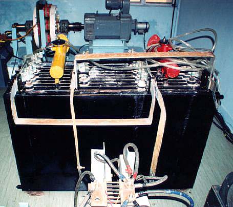
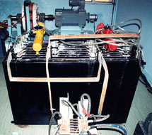
Photo 1
Alternating current power SPG with step up transformer
Click image to view enlargement.
|
|
|
|
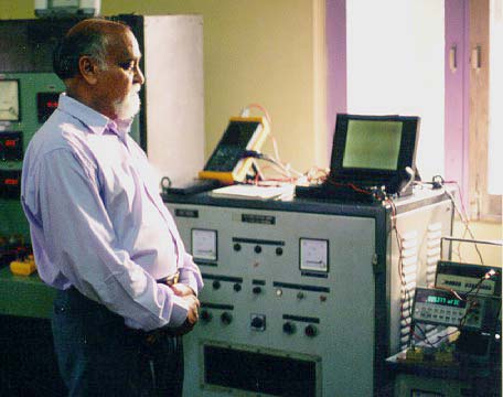
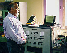
Photo 2 Direct
Current version of SPG during measurement verification December
1997
Click image to view enlargement.
|
|
The
next generation SPG will use electrical output for feeding a Faraday
motor mounted on the same shaft to achieve self-sustaining operation. Certain
specific configurations of magnetic fields from rotating electromagnets and
electrical conductors have made it possible to construct an SPG that produces ac
power presently in the same range as the SPG producing dc power with an
efficiency of about 250 percent. Photograph 1 shows the SPG that produces ac
power and Photograph 2 shows Mr. Grotz sitting behind the SPG that produces dc
power.
The
SPG producing ac power has a specific configuration of rotating
magnetic circuits with respect to the conductor producing ac voltage through
electromagnetic induction.
Table
1, where test results on the ac SPG are given, shows that the ac
electrical power generated in the SPG is 2.5 times the mechanical input applied
at its shaft over and above the constant losses due to windage and friction. One
conclusion of this advantage is that rotation of the entire magnetic circuit,
and the specific path that the load current takes within the magnetized iron
core, is responsible for over-unity efficiency in the SPGs. A similar conclusion
was drawn on the rotation of the magnetic field where, in an experimental setup
when part of the magnetic circuit was fixed with the Earth's reference frame,
the efficiency of the SPG decreased. In the ac SPG, the conductor in which the
voltage is induced does not form a co-rotating system (as it does in the dc SPG),
and yet the machine produces ac power at over-unity efficiency.
Table
1. Tests Results of the SPG Generating AC Power December 1993
- Speed (rpm) 1960
- EMP on no load (volts) 1.98
- Electrical input to driver motor (windage and friction) on no load (watts)
2145
- Electrical input to drive motor on load (watts) 3575
- Rise in mechanical input to the SPG from no load to on load (watts) 1430
- Mechanical input to drive motor on load with the combined efficiency of
0.8 for the drive motor and the coupling (watts) from step 4 3575 x 0.8 =
2860
- Output electrical current on load from the SPG (amps) 1493
- Electrical output (I2R) from 1 and 2 in watts 1.98 x 1493 = 2957
- Magnetic excitation power (watts) 676
- Total input to the SPG from 6 and 9 in watts 2860 + 676 = 3536 watts
- Efficiency of the SPG (ratio of electrical output to corresponding
mechanical output, divided by the efficiency of drive motor and coupling)
from steps 8 and 5 2957 / 1430 x 0.8 = 2.584 Improvement in the Direct
Current SPG's Design
|
|
|
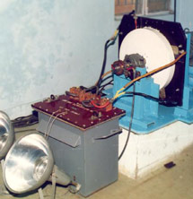
Photo
3 Low Voltage, high Current application using the Tewari SPG
as a power source.
Click
image to view enlargement.
|
|
|
|
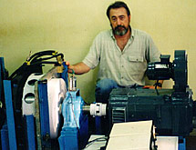
Photo
4 Paramahamsa Tewari observing SPG test and measurement
verifications.
Click image to view enlargement.
|
|
In
the Space Power Generator there is a loss of power produced in the
generating element as the load current is pushed against the back EMF in the
motor element. Tapping additional power from the SPG after certain modifications
in the output circuit of the machine solved this problem. Table 2 shows that
efficiency greater than 300 percent is achieved when the ratio of electrical
output and the corresponding mechanical power input to the SPG (over and above
the windage and frictional losses) is taken.
Table
2 Tests Results of the SPG Generating DC Power
- Speed (r/min) 2100
- EMF on no load for circuit 1:
1050 mV dc
- EMF on no load for circuit 2:
1281 mV dc
- Output current from circuit 1:
1387 A dc
- Output current from circuit 2:
534 A dc
- Total electrical output from 2, 3, 4, and 5: 2140 W
- Rise in drive motor's input corresponding to electrical output (over and
above power for windage and frictional losses): 825 W
- Efficiency from steps 6 and 7 with 0.8 as combined efficiency of drive
motor and coupling: 2140/824 x 100/0.8 = 324%
The
SPG is proven technology The SPG is proven technology that
produces 200-300 percent over-unity energy. The SPG theory has been tested and
proved. It is time, now, to build a prototype system and to work on improving
the concept to develop a product that can be used in every household.
Test
Report
Scientific And Spiritual Research Council
Vinodini
Nivas
Karwar, Karnataka India
December 18, 1997
No
Load Tests
A. The SPG was run at 700 rpm.
With electromagnets energized using 18 amps dc current the following was
observed:
- The emf developed = .509 vdc (I)
- The input current to drive dc drive motor (DM) increased by .3 A dc. This
increase in input is attributed to eddy currents due to slight
non-uniformity of the magnetic field in the air gap.
B. The machine was run at 1050
rpm with the excitation of the electromagnet kept constant at 18 A dc.
- The emf developed in the SPG was .762 vdc (II)
From (I) and (II) it is seen that the emf generated at constant excitation is
directly proportional to speed.
C. The
SPG was run at 2690 rpm.
- The no load current to the DM was 8.55 amps (III).
- The no load voltage at the DM was 346.9 vdc (IV)
From (III) and (IV) the no load input of the DM while coupled to the SPG that
accounts for windage and friction, at the speed of 2690 rpm = 2966 watts. (V)
Load
Tests
D. The machine
with shunt connected across the output terminal of the SPG was kept at constant
speed of 2690 rpm when the test described in C above was repeated. The
electromagnet was energized at 18 amps dc and the following was observed:
- Input current to the DM = 15.5. A dc (VI)
- Voltage at the DM's terminal = 339.9 V dc (VII)
- The shunt load voltage - 47.25 mV dc (VIII)
- This circuit includes the output leads and contact resistance of two
sets of sliding contacts (copper-graphite brushes)
- On load input to DM =15.5 x 339.9 = 5268.45 W (IX)
Efficiency
E. EMF
of the SPG at 2690 rpm from (I) = (2690 x .509/700) = 1.956 vdc (X)
DC current output from the SPG from (VIII) measured with a calibrated shunt
(2000 A = 50 mV) = 47.25 x 2000/50 = 1890 A dc. (XI)
From (X) and (XI), the output of the SPG (total including heat generated in
the SPG and load circuit) = 1.956 x 1890 = 3696.8 watts. (XII)
Against 3696.8 watts of output power from the SPG as above, the corresponding
rise in DM output from (V) and (IX) = 5268.45 = 2966 = 2302.45 watts
(XIII)
Over and above the windage and friction at any speed, each kW of additional
power to the drive motor of efficiency 0.8 (DM's efficiency at this loading),
from (XII) and (XIII) will produce, 3696.8/2302.45 x 10/8 = 2 kw of power.
The expression of efficiency of the SPG will be
efficiency = output/(output/2 + losses) (XIV)
Heat
Balance
From input to DM on no-load supplied towards windage and frictional heat and
power output (I2R) of the SPG, total heat output of the SPG, from
(XII) and (V) = 6662.8 watts (XV),
Whereas input on no load to SPG is 5268.45 watts (from (IX)) which shows that
1394.35 watts of additional energy is generated in the SPG.
From (XV) and (IX), the overall energy efficiency = ((6662.8/5268.45) x 100)
= 126.6%
Test measurements made and observed by:
Toby Grotz
Wireless Enginering
Test equipment included calibrated instruments as follows:
|
Empro Calibrated Current Shunts
|
|
Fluke 97 Scopemeter and Data Acquisition
|
|
Fluke Y8100 AC/DC Current Gun Probe 0 - 200 amps
|
|
Hewlett Packard 3400A RMS Voltmeter
|
|
Hewlett Packard 3466A True RMS Digital Voltmeter
|
India
Trip Report
August 2000
Tewari's
machine is as usual measuring overunity. 9 KW electrical energy in
and 9 KW electrical energy out plus 3 - 4 KW heat out. (I squared R loss across
the brushes). Tewari has found a method of reducing the effect of Lenz's law.
His next model will be a substantial improvement over the current unit.
The current unit was funded for 3 years by the GE of India, Crompton Greaves
Ltd. CGL admitted in an email to me from the a Manager, who is an electrical
engineer with a background in motor and generator efficiency measurements, that
the SPG was over unity. CGL is not pursuing the invention because they do not
see a market for a low voltage high current machine.