1, 000, 000 VOLTS
This Page taken from http://hometown.aol.com/lyonelb/marx.html
MARX GENERATORS, MARX BANKS, IMPULSE VOLTAGES
GENERATORS
A Marx Generator is a clever way of charging a number
of capacitors in parallel, then discharging them in series. Originally described
by E. Marx in 1924, Marx generators are probably the most common way of
generating high voltage impulses for testing when the voltage level required is
higher than available charging supply voltages. (
Jim Lux )
| Le choc de tension est la generation d'une haute tension
impulsionnelle de 10 kV a 10 MV avec un temps de montee de 1 nS a 1 mS
et un temps de descente , ou jusqu'a la coupure, de 100 nS a 1 s.Les
chocs sont uniques ou repetitifs a des intervalles de 10 mS a quelques
minutes. |
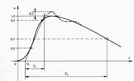 |
| Choc de tension impulsionnelle O1 = origine
conventionnelle du front - T1= duree conventionnelle du front
- T2= duree conventionnelle de la queue.
Typical Impulse Waveform O1=Nominal
origin T1=Nominal duration of wave front T2=Nominal
duration of wave tail
La fonction uc(t )correspond a une difference de deux
exponentielles dont les constantes de temps sont differentes et
conduisent à la forme du choc.
|
![[Image]](marx_pict0.jpeg) |
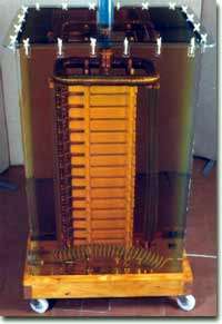 |
| 1.3 MV -North Star Generator |
An oil-insulated 1.2MV Marx Generator |
| North Star |
Magnavolt Technologies |
The charging voltage is applied to the system. The
stage capacitors charge through the charging resistors (Rc). When fully charged,
either the lowest gap is allowed to breakdown from overvoltage or it is
triggered by an external source (if the gap spacing is set greater than the
charging voltage breakdown spacing). This effectively puts the bottom two
capacitors in series, overvoltaging the next gap up, which then puts the bottom
three capacitors in series, which overvoltages the next gap, and so forth. This
process is referred to as "erecting". A common specification is the
erected capacitance of the bank, equal to the stage capacitance divided by the
number of stages.
The charging resistors are chosen to provide a typical
charging time constant of several seconds. A typical charging current would be
in the 50-100 mA range. The charging resistors also provide a current path to
keep the arc in the spark gaps alive, and so, should be chosen to provide a
current of 5-10 amps through the gap.
For example, with a stage voltage of 100 kV, a desired
output voltage of 1 MV (i.e. 10 stages), the charging resistors should be about
20-40 kOhms (corresponding to an arc current of 5 to 10 Amps). If the capacitors
were 1 uF, then the discharge time constant would be 20 milliseconds, much, much
longer than the 50 microsecond time constant of the standard test impulse. This
example generator would have a stored energy of 5 kJ/stage or 50 kJ for the
total system. At a charging current of 50 mA, it would take at least 20 seconds
to charge the entire stack. ( Jim Lux ).
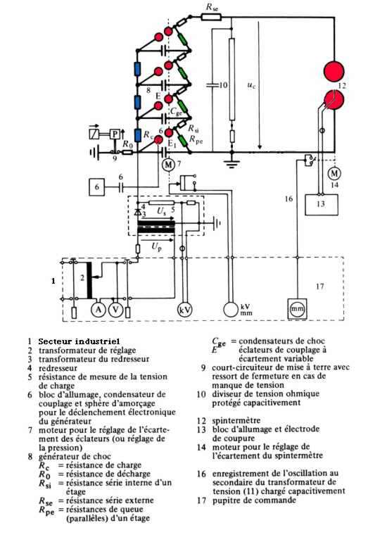 |
| 6 Trigatron
Rsi and Rpe
= wave shaping resistors
Rsi
= front resistors ( for the control of the wave front duration )
Rpe
= tail resistors : control the time to half value for the impulse
waveshape. The standard lightning impulse tail time is 50
microseconds+/- 20 %
Rc
=charging resistors (high ohmic value )
|
 |
| Uc(t ) |
Ug0 |
a |
h |
Q |
Formules
/ formulas set (Aguet M. , Ianoz M. ) |
Abaques
/ abacs set (Aguet M. , Ianoz M. ) |
| Tension de choc aux bornes de l'objet en fonction du temps |
Tension maximum de charge du condensateur de choc ( Cg) |
Facteur determinant l'allure de la tension de choc |
Facteur determinant le rapport entre la tension de charge Ug0
et la tension maximum de choc Umax (rendement)
|
Coefficient determinant le temps |
Formules de passages permettant de determner la forme de
l'onde de choc
Uc(t ) a partir des
caracteristiques du generateur et reciproquement
|
Tabulation de l'equation pour differentes valeurs de a |
| |
|
Waveform factor |
Efficiency |
Coefficient of time |
|
Equation tabulation |
|
| A.M. Angelini - Calcolo rapido degli elementi delle forme d'onda
del generatore di imulsi - Elettrotechnica , vol 28 , N° 10, maggio
1941,pp 252-258 |
| Calculation of coefficients from resistance and
capacitance values. Wavefront and Wavetail times of practical waveforms. |
One stage generator - Formulas set
: schema II .
If Cg= 0.125 µF Cc=1
nF Rs2 = 360 W Rp=
544 W
--> T1 and T2 ?
Q = (CgCcRs2Rp)1/2
= (0.125.10-6.10-9.360.344)1/2 = 4.9 µsec
h = 1+ C1/Cg.(1+Rs2/Rp)
= 1 + 10-9 / 0.125.10-6 (1+ 360 / 544) =
1.013 (1)
a = 1/2 RpCg h
/ Q = 1/2. 544.0.125.10-6.
1.013 / 4.95.10-6 = 6.9 (1)
If a = 6.9 abacs show T2/
Q= 10.1 so T2=10.1.4.9= 50
µsec
If T2/T1=45 abacs show T1=
50 / 45 = 1.1 µsec.
|
One stage generator - Formulas set
: schema II.
If Cg= 0.125 µF Cc=1 nF Tcr=250
µsec ( front time) Th = 2500 µsec (tail time) (switching
impulse)
--> Rs2 and Rp ?
Top abac shows, for Th / Tcr = 2500 µs/ 250 µs = 10 , the value
of a parameter is 4. For this value Th/ Q
=7.40, so Q = 2500 / 7.40 = 338 µs
X = 1 / a 2(1 + Cc
/ Cg) = 1 / 42 ( 1 + 1. 10-9 /
0.125.10-6) = 0.063 ( 1)
--> Rs2= {Q / Cc}.
(1-(1-X)1/2) = 4.338.10-6/10-9
.(1-(1-0.063)1/2) = 43.3 kW
Rp= {a.Q
/ Cg+ Cc} . (1+ (1-X)1/2) = {4.338.3.10-6
/ 0.125.10-9}. (1 + (1-0.0063)1/2) = 21.1 kW
|
8 stages generator
n stages Cg =Cge/ n Rs2=
nRsi+Rse Rp = nRpe
n = 8 Cge = 1 µF Cg
= Cge / 8 = 0.125 µF Cc = 1nF
(if T1/T2 = 250/2500 µs) -->
Rsi = 15 W Rse
=43.2 kW Rse = 8Rsi+Rse
= 43.3 kW Rpe = 2.6 kW
Rp=21 kW
(if T1/T2 = 1.2/50 µS) -->
Rsi= 15 W Rse
=240 W Rse = 8Rsi+Rse=
360 W Rpe
= 68 W Rpe=544
W
If Umax = 800 kV
then stocked energy is W = 1/2 CgU2 = 1/2.0.125.10-6
(800.103)2 = 40
kJ
|
Applications
Selon la forme de l'onde impulsionnelle engendree par le dispositif ( forme
qui depend des valeurs choisies pour les resistances de front et de queue) on
distingue :
Le choc de manoeuvre (switching impulse):
T1/T2 = 250/2500 µs -
temps de montee : 250 microsecondes , temps de queue 2500 microsecondes.
Simulation des surtensions de manoeuvre .Essais dielectriques de choc.
Le choc de foudre ( lightning impulse)
:T1/T2 = 1.2/50 µs-
temps de montee : 1,2 microseconde , temps de queue 50 microsecondes.
Simulation des surtensions de foudre.Essais dielectriques de choc
Le choc a front raide (Steep front chopped
wave) : temps de montee : 10 nanosecondes, temps de descente : 250
nanosecondes.Simiulation des surtensions engendrees par des eclateurs de
reseaux electriques lors de leur amorcage.
Simulation des perturbations electromagnetiques , en particulier les
ondes NEMP ( Nuclear Electromagnetic Pulse )
engendrees par des explosions nucleaires de haute altitude.
>What are the real world uses of Marx Generator?
Production of artificial lightning, mostly. The 3 MV
unit at Mississippi State University is about four stories tall and has twenty
stages, each with its own set of spark gaps and a couple of suitcase-size
capacitors. The capacitors are charged in parallel through a particularly
troublesome resistor network and then discharged in series through the spark
gaps.
The waveform is shaped by an RC network at the output
of the generator to conform to whichever IEEE or CIGRE standards for lightning
or switching surge is being reproduced at the time. The actual waveform is
recorded ona digital storage oscilloscope for documentation purposes.
Depending on the voltage, the device takes something on the order of thirty
seconds from the start of the charging process to the discharge. The discharge
is initiated automatically when the voltage reaches the desired level. This is
done by initiating an arc across the bottom sphere gap pair with a 4 kV
impulse.
If a large (several meter) gap is being used at a
high voltage, the report of the machine can be heard at some distance across
the campus. Ear protection is now mandatory, but it's an unfortunate fact that
many high voltage engineers suffer severe hearing loss during their careers.(M
Kinsler)
They are used to generate high voltage to simulate
lightning, EMP (byproduct of Nuclear explosion) and to drive particle beam
accelerators. They are also sometimed used in big laser's, nuclear effect
machines (Gamma and x-ray sources).
Exemples de realisation
1-Le generateur de choc du laboratoire Ampère
( Ivry - France ) , 1935
Un des deux premiers accelerateurs de particules francais ( Frederic
Joliot Curie , 1937) : photo
65 k
Dans un vaste hall, haut de 18 mètres, entièrement metallise, de façon
a constituer une cage de Faraday, se dresse la colonne, haute de 13 mètres,
du generateur de choc de 3 000 000 V. Poids : plus de 20 tonnes.
Le courant alternatif a 30 000 V , redresse par kenotron, charge en
parallèle des groupes de condensateurs etablis en series de 5, en sorte
que la decharge des eclateurs intermediaires se produit a 150 000 V .
La totalisation a 3 000 000 V s'effectue donc en 20 etages ( 100
condensateurs) .
C'est dans le Laboratoire de synthese Atomique d'Ivry , qui est la
transformation des Laboratoires Ampere de la Compagnie Generale
d'Electro-Ceramique, ( 1936), que fut signe l'acte de naissance de
l'energie nucleaire ( CNRS). Une partie de son instrumentation historique (
spheres de decharge et colonnes de condensateurs) est transferee, en reserve, au
musee Electropolis
de Mulhouse.
2-Realisations personnelles (hvlist)
Design equations are given in Craggs & Meek,
"HV Laboratory Technique", 1954 (unfortunately out of print, but
most libraries have it).
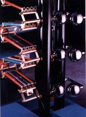
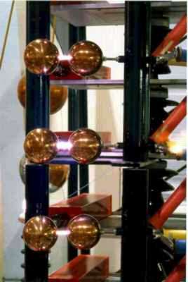
[Marx voltage multipliers] One
of my Marx generators consists of six stages, the capacitors all hand made
from long strips of mylar and aluminum foil rolled into cylinders around PVC
pipe. These form the rungs affixed to two PVC uprights. The charging resistors
are all 1 megohm and the spark gaps are metal balls running diagonally from
rung to rung. The trigger is nothing more than a motorcycle spark coil
connected to a 12 volt supply via momentary contact switch (
from Lawrence M. MacCary, 1996).
I've done this also. I've built two using the polyeth.
caps. of 20 stages each. The high energy one creates a real bang when it
fires.I created a new design which eliminates the resistors (and their losses
and consequent slow charging, leakage etc.) The design is based on an idea I
once saw in the Amateur Scientist in Sci. Am.which was for a pulsed U.V. laser
utilizing a Blumlein switch.Basically, the resistors are replaced by chokes.
I've found that inductance approaching 1 mH is sufficiently large for the
7000pF caps. to allow O/P voltage to reach about 95% of ideal. The rule is
that the lower the capacitances, the larger must be the chokes to compensate
(they effectively do a D.C. supply disconnect job). The unit I built stands
about 2 feet high, and generates sparks about 7-8" long (about 270kV).
The tower also emits a MASSIVE RF pulse when it fires - if you build one,
DON'T operate it anywhere near any electronic gear. The spark gaps are formed
from thick copper wire with the end bent into loop, the end of the loop being
equivalent to your spheres.My Marx is self triggering (careful spark gap
adjustment) ( from Malcolm Watts, 1996).
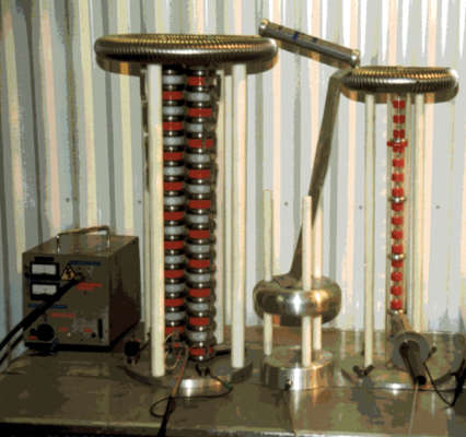
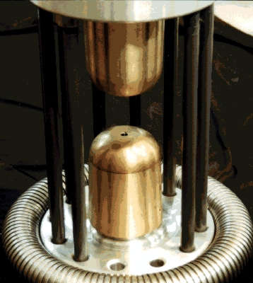
Basically, I constructed the towers from perspex
(acrylic) with a stage height to suit the home rolled capacitors. As a result,
the towers are quite short and hold 22 capacitors of around 5nF each which can
be charged up to around 18kV each.Tower height is around 600 - 700mm. Max
discharge length with this storage is around the 250mm mark (a bit less than
half the height of the tower). With higher voltage rated caps, the discharge
length could be improved substantially. I used single-layer chokes wound on
ferrite rods instead of resistors to facilitate fast charging (this was the
"novel" bit) and thick copper wire with one end curled as a spark
gap electrode and the other end as a pressure contact to the capacitor (these
are extended foil types).The general construction method for these caps was
published in the March issue of the British magazine "Electronics World
and Wireless World".I should note that
this is a dangerous device. Total energy
storage prior to firing is about 17 odd Joules with the figures given. It not
only goes off with a real detonation (ear protection a must), but can give a
whale of a shock if you accidentally trigger a portion of it while reaching
out with a screwdriver to fire a gap part way up. Additionally, it emits a
HUGE RF pulse and potentially damaging ground current. I lost count of the
gearI had to repair after delightedly testing the first one in a work shop
full of test equipment. The spark is a real lightning bolt. It is also
oscillatory in nature (you can sometimes see this on a photograph and it could
be easily shown with a panned camera). I have also charged the towers up with
opposite polarities and fired them at each other. No ball lightning yet but
I'm betting on getting there if it can be done. Using the choke setup, you can
vary the resonant frequency of each tower. I think it would also be capable of
running directly from AC if the choke inductances are tailored right and the
spark gaps were more robust ( from Malcolm Watts,
1996).
From Jochen Kronjaeger,
1998
My specimen has four caps (same as I use with the
tesla coil) connected by 20mOhm resistors (2x10MOhm). The three spark gaps are
just bent wire. The caps are charged to nearly 30kV through another 500MOhm
resistor, giving a theoretical output of 120kV; the spark length is about 10cm
(4"). The fact that the resulting spark length is much shorter than e.g.
with the 100kV cascade has (at least) two reasons: first, pulse voltages
always have shorter spark lengths than DC (the spark has not so much time to
develop). Second, the caps can never be charged to full 30kV within finite
time
Date: Fri, 1 May 1998 From:
"D.C. Cox" To: hvlist
Subject: Marx Bank
Basically they are HV caps charged in parallel and
discharged in series. Stage parallel charge separating resistors are typically
40-50K ohms and series wave-shaping resistors are usually 100-400 ohm values.
A good protection scheme is necessary between power supply and the actual cap
bank as the reflected standing wave as the spark gap fires can damage the
supply. In our commercial systems we use inductors, resistors, and then
actually use a HV relay to disconnect the charging supply from the cap bank at
0.5 seconds before firing. We use a 558 timer with optoisolated triacs to do
the timing functions after the firing button is pressed. DR.RESONANCE@next-wave.net
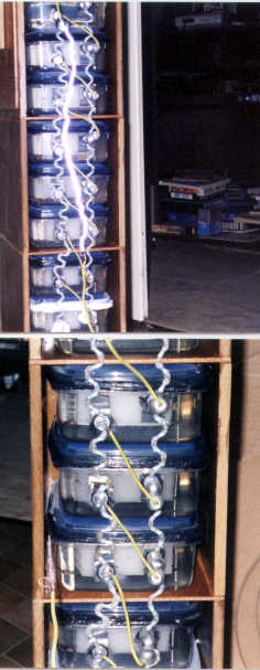
3- Generateur de Marx du Dr G. Hublart (
g.hub@free.fr )
 |
 |
| Generateur de Marx realise par empilement de 9 condensateurs THT (
aluminium / polyethylene / huile minerale dans boite Tupperware ) |
This Marx' is powered by a 12 V induction
coil |
| Eclateurs regles a 10 mm sauf l'eclateur d'amorcage qui est regle a 9
mm. Decharge de 300 mm ( 270 kV - 300 kV ) |
5 Mohm resistors are embedded in hot glue.
Spark-gaps = 10 mm |
4 - Refurbishment of the Ferranti 800kV
Impulse Generator :
The Ferranti Impulse Generator comprises of two
vertical columns each carrying four high voltage capacitors. The capacitors
are charged in parallel to 100 kV and then discharged in series to give a peak
output voltage of 800 kV. The performance of the generator had deteriorated
over a number of years due to the failure of the high-voltage switches or
"polytron gaps" .The traditional method of firing impulse generators
is to use a system known as a "trigatron". In this system, the main
high voltage sphere gap has a third triggering electrode, hence the name
"trigatron". The impulse generator is now fully operational ,
capable of producing 800 kV electrical surges.( Dr
Ken S. Smith )
> Can anyone tell me how quickly the spark gaps
(triggered or not) in a Marx generator will break down ? What is the largest
dV/dt I can expect on the output ?
Well, the spark gap breakdown is widely dependent on
gap length, gas,overvoltage, supply of initial electrons etc, but for a 1
mm-gap, you can have it of the order of nanoseconds.The lagerst dV/dt? I don't
know the largest, but in standard high-voltage testing you use a rise-time of
1,2 microseconds and apply MV, which gives a dV/dt of 10E12 V/s.
Question From: Gary
Weaver ( Hvlist, 1997)
I don't know the correct answer to your question. But
if I were building a Marx generator I would use something like a switch to
discharge the 1st spark gap. The switch could be a jumper wire. I would short
out the 1st spark gap with the wire and it would cause all the other spark
gaps to discharge and produce the high voltage output spark.
Answer From: Malcolm
Watts ( Hvlist, 1997)
You don't need a triggered gap at all. I have built
two Marx banks that work just fine with careful gap setting. The first one to
fire should be at one end (usually the bottom) so its setting defines
total energy in the discharge. The models I built used chokes instead of
resistors and can be run on AC with robust gaps. I would not recommend using
jumper wires or getting anywhere near a Marx bank to fire it. They are
extremely dangerous. You can end up with the full output voltage
tracking along your jumper wire back to your hand. There is virtually no
inductance in the discharge path and the currents are enormous. This is real
lightning.
Answer From : TimRaney
, TCBOR ( Hvlist , 1997)
On using a jumper wire to trigger the first gap of a
Marx generator is probably not a really good idea. A three electrode trigger
gap for the first gap is preferable or a hydrogen thyratron would do the
trick. I tried a Marx circuit design with all gaps being the same and didn't
have much luck, but I hadn't done my homework on the circuit. Frungel's book,
"High Speed Pulse Technology," 1965, is a great reference and
includes Marx generator design, along with some of the older physics texts
that cover using a Marx generator as a HV source for a particle accelerator.
Answer From : Richard
Hull , TCBOR
( Hvlist , 1997)
I agree, simple gaps, carefully setup, are definitely
the way to go here for amateur work.
Sites - Liens ( Websites - links)
4-Bibliographie / Literature
W. James Sarjeant and R.E. Dollinger -"High Power Electronics"-
1989 , Tab Prof and Ref Books, 392 pp -ISBN 0-8306-9094-8
Frungel's book -"High Speed Pulse Technology " - 1965
Craggs & Meek, -"High Voltage Laboratory Technique" - 1954
Bazelyan & Raizer -"Spark Discharge"-(CRC press)
Meek, J. M. and Craggs, J. D., "High Voltage Laboratory
Technique", Butterworths, 1954, 404 pp
Kuffel, E., and Abdullah, M., "High Voltage Engineering",
Pergamon Press, 1970, 377 pp
Heilbronner K.W - Firing and Voltage Shape of Multistage Impulse Generator-
IEEE Trans,Power App.Syst., vol.PAS-90,num 5,1971, pp 2233-2238.
Pai, S. T, & Zhang, Q., "Introduction to High Power Pulse
Technology", World Scientific, 1995, 307 pp
Aguet M. , Ianoz M. - Generateurs de hautes tensions transitoires -in
Traite d'Electricite,Volume XXII, Presses polytechniques et universitaires
romandes, 1990,Lausanne
Ensemble d'experimentation haute tension, Publ. Messwandler-Bau,
GMBH, Bamberg.
Michel Ellenberger- Quel destin pour le laboratoire des Joliot-Curie ? - La
Recherche , sept. 1994, vol. 25, n° 268 , p 948
Pinault Michel - Frederic Joliot -Curie - 2000 , Editions Odile Jacob
Pour me joindre sur mon Email : lyonelb@aol.com.
ACCUEIL
(RUHMKORFF)
VAN
DE GRAAFF |
RESONATEUR TESLA |
CASCADE GREINACHER |
PAGE
GENERATEUR DE FELICI
1999, 2001 © Lyonel Baum
lyonelb@aol.com.