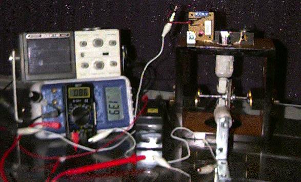
(The coil in front is to read the frequency)
| Parts | This Motor | John Bedini's Diagram |
| Diode | 1N914 | 1N914 |
| Coil Core | Welding rods | Welding rods |
| Main Coil Gauge | 23ga | 23ga |
| Trigger Coil Gauge | 26ga | 26ga |
| Transistor | MPS8099 | MPS8099 |
| Coil Width | 1" | 1" |
| Coil Length | 1.5" | 1.5" |
| # of turns on Coil | 560 | 450 to 800 |
| Resistor | Best in this one at 270 ohms | Default 680 ohms |
| Rotor Size | 2.5" | 2.5" |
| Magnets | 6/8 Ceramic Round | Unknown thickness -5/8 x 5/8 |
| Bearings | Vcr Flywheel type mount | Skate bearings? |
| Rotor Weight | ~1/4 lb | Unknown |