 |
 |
 |
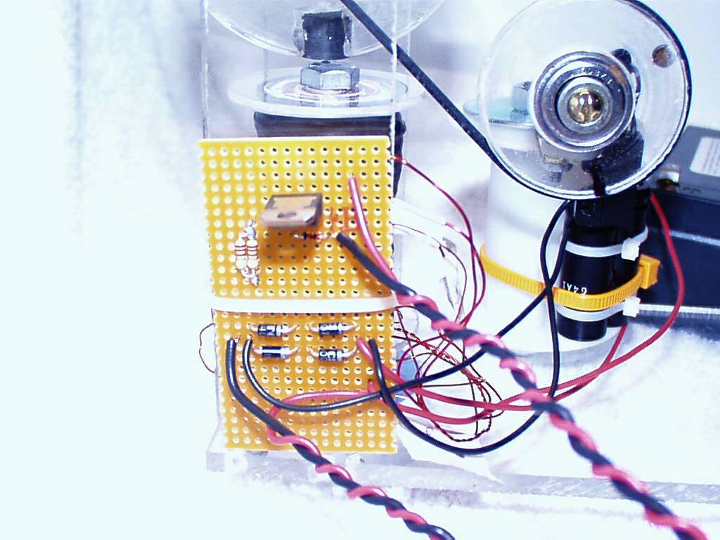 |
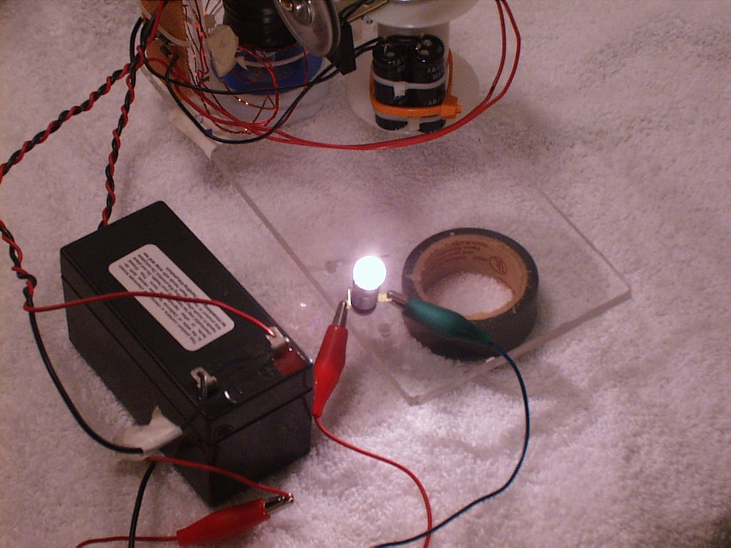
| Here is a photo of the bulb being hit with a 30 volt pulse from the capacitor. It is VERY bright. This is the pulse that would normally be sent back to a dead battery to charge it. The longer you wait before triggering the switch, the higher the voltage will go. In one test, I blew the fuse in my test meter with a pulse of over 200 volts. In fact, I also blew a 120 volt nightlight bulb by letting the voltage get too high. | Here is a closer look at the capacitors. They are photoflash capacitors in parallel to equal 350 uF. You can see the magnetic switch that triggers the pulse to the recovery battery. It is mounted behind the pulley, and a very small magnet glued to the pulley operates it. This whole assembly is mounted on an old plastic wire spool attached to the plexiglas base. Also in the background you can see a better view of the coils. | This picture shows a front view of the device. I am using a small 12 volt rechargable gelcell for power. And for demonstration purposes, I have a 14 volt bulb to visually display the pulses that would normally go to the battery being recharged. | This is the controller board. The transistor is a TIP3055, the diode is 1N914, and I have 2-220 ohm resistors to make the equivalent of a 1/2 watt 110 ohm resistor. The bottom half of the controller is the 1000v PIV full wave rectifier circuit connected to the capacitors. 4- 1N4007 diodes. |
 |
 |
 |
|
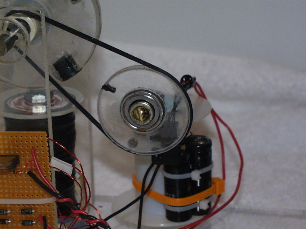
| This is a closeup of the pulley. I made this from 1/4" plexiglas. I chucked it up in the drill press and cut the groove with a file as it spun. Then I drilled a hole in the center for a bearing so it would spin very easily. You can see the small magnet glued to the back of the pulley. It triggers the magnetic switch as it rotates past. | This is a 3" plexiglas rotor with 4 doubled 1/2" ceramic magnets. On the rotor you can see the small pulley made from CPVC and epoxied to a nylon washer, centered on the shaft and glued to the rotor. The shaft is a 5/16" steel rod, and the bearing(not shown) is inside the rotor. It is a precision inline skate bearing with ABEC-3 grease. Also, you can see the belt for the pulleys. It is off of an old VCR. | Here is a sideview of the device. You can plainly see all the components. To the left, you can see the controller circuitry. It also has the 1000v PIV rectifier made from 4- 1N4007 diodes at the bottom of the controller board. 350uF worth of photoflash capacitors to the right. And to the back is the coil assembly. The trigger and pwer coils are wound bifilar, and the recovery coil is wound on top, but connected with reverse polarity. All coils are 450 turns. |