The Bedini Pulse Motor Of Gene Nelms
|
|
or Download complete Movie - Description of Motor 1.65 MB
CLICK PHOTO for Larger Image
I could not get this motor to work the 1st time, but see below what was wrong. Now it works great!
 |
 |
| 3 inch rotor, 2- 1/4" pieces | Magnets were not strong enough 1st time |
 |
 |
 |
 |
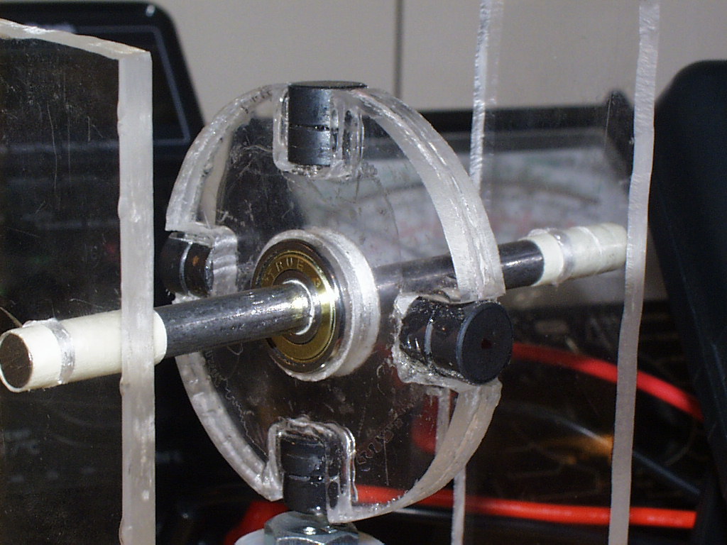
| Pic#4- This is the failed
first rotor. As you can see, I made the rotor from a plastic
wheel and 2 bearings epoxied in place. The magnets were too weak. I was not sure just how strong the magnets had to be, so it was pretty much trial and error. I thought that the coil was too weak and even rewound them 3 times. I was sure it was the coils since I got good repulsion when connecting the coils directly to the battery (like an electromagnet). Further checking with my oscilloscope showed that the transistor was NOT switching, so I had 2 choices, I could either add more turns to the coil or add stronger magnets. I first added about a hundred more turns to the coil. This added some additional voltage, but not nearly enough to make that silicon transistor switch. So, I took another look at the magnets. This was the missing piece of the puzzle. The magnets were from Radio Shack, and were not even close to giving the amount of voltage required to switch the transistor on and off. Increasing the number of turns on the coil produced more power, but still not enough. The solution was to build a new rotor with stronger magnets. Radio Shack magnets were still not strong enough on the new rotor, so I added small Neodymium Iron Boron magnets to the stack, thus producing the required transistor junction voltage |
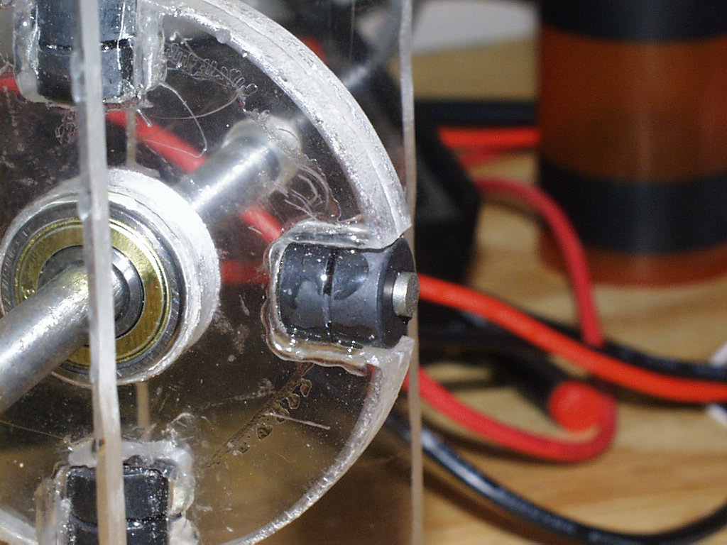
Pic#5- The 1/2"
Radio Shack ceramic magnet stack on the new rotor, with the addition of
the rare earth magnets now epoxied in place. |
 |
 |
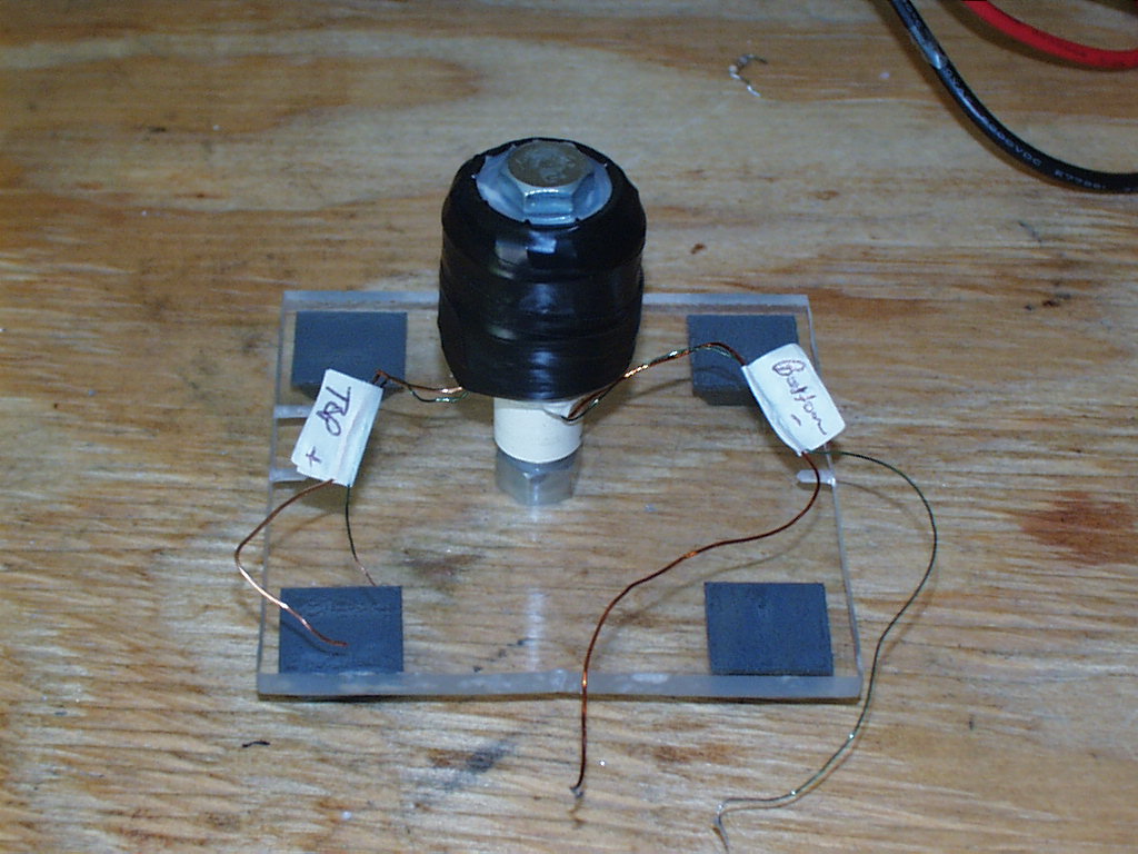
| Pic#6- This is the coil
assembly. It consists of power coil and pickup coil, wound all
one direction in a bifilar fashion. The power coil is 23 gauge magnet wire and the pickup coil is 26 gauge magnet wire. Once again, standard Radio Shack parts. Coils wound on a 3/8" bolt 2 1/2" long. Then mounted on plexiglass frame. The white item under the coil is a standoff made from pvc pipe, in this case it was required to bring the coil closer to the rotor. |
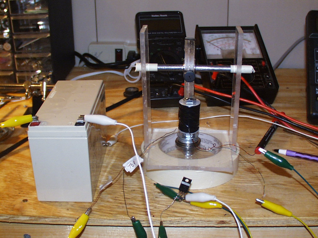
Pic#7- This is the
completed motor ready to run. |
 |
|
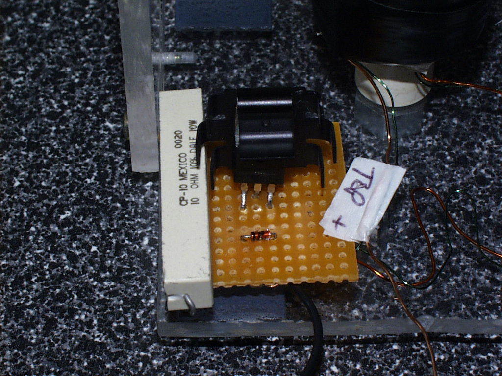
| Pic#8- This is the
controller circuit. It consists of a Radio Shack TIP-3055 Part #276-2020, a 1N914 diode, and I am using a 10 watt- 10 Ohm resistor for testing. Of course I will try many different resistor values, voltages, and transistors; but for now, this is what I had on hand and it worked. |
Thanks Gene! |