By David Mason More Information Here!
THE TIME ENERGY PUMP - V 1.2
Following my experiment with V1.0, I came to the conclusion that if energy was being tapped it would be through the coil, and if so, wouldn't a longer coil tap more energy?
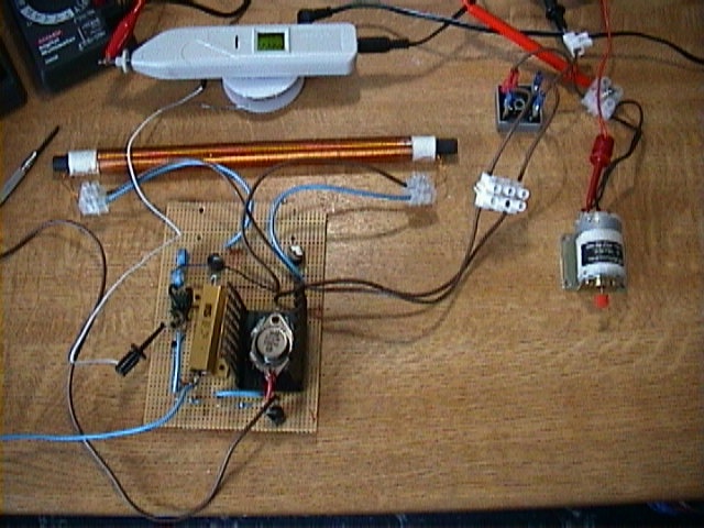
I used the same circuit from version 1.0, but this time I used a Bifilar coil of 140 turns of 0.56mm wire. Also I added a 25amp bridge on the output to run a DC motor.
During testing the current meter reading the current taken from the battery started to read a minus or reverse current flow. Indicating that the circuit was producing energy which was travelling backwards into the battery. It was suggested to me that the reading could be false due to the high frequency, so I placed a 1uf capacitor across the terminals of the meter to drown out any RF noise. The reading remained the same. I also used a analogue meter, this also confirmed a current drop when the circuit was under load, but not a minus current reading.
Question: How could a reverse current appear since there is a diode on the input of the circuit to stop any reverse current?
I ran this circuit for one hour and the battery voltage did not change. Then I noticed that the transistor and power resistor were stone cold. The motor was still going strong.
The current across the meter reads 11 amps, how is this possible when the meter can only read 10amps (with 10 amp fuse)? Obviously a false reading, however on further tuning the output current could read 19amps and then read error as it went of the scale.
These results bring a clear conclusion. The device does give a current drop when under load, and the current does not change under load, but there cannot be a reverse current. If this was so the battery would never run down, it would also mean that no current at all was being taken from the battery, and the motor would easily burn out at 11 amps. The only things that give me some hope is that the transistor and power resistor remain cold.
I will try a self running test to make sure.
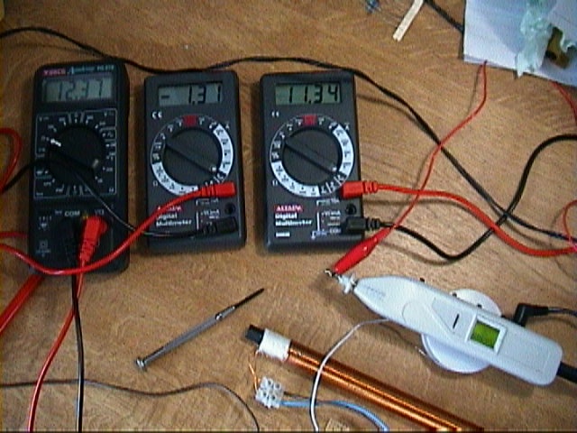
THE SETUP

The left hand meter shows the battery voltage, the middle meter show the current drawn from the battery, and the right hand meter shows the current across the load (DC motor).
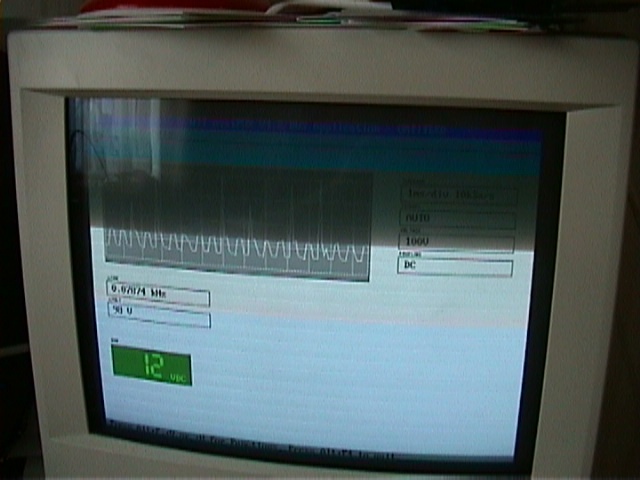
This is the
output signal.#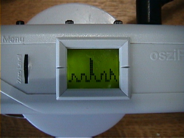
(This pic is a bit unclear, I will later post a screen copy)
If you have any thoughts or comments on this experiment, please email me.