By David Mason - More Information Here !
THE TIME ENERGY PUMP
Created 20/04/00 - Last Update 29/04/00
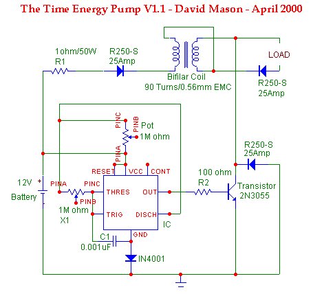
The purpose of this circuit is to create large amounts of Back EMF which can be used to recharge its own battery, etc... At the bottom you can see the idea behind the designs courtesy of J Naudin.
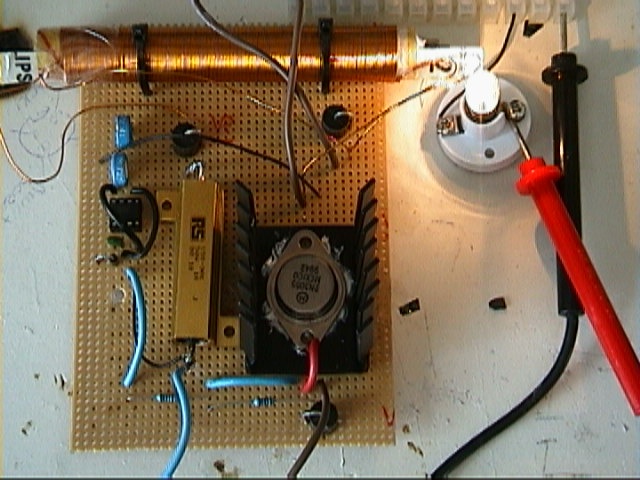
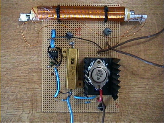
28/04/00 - This Is The Completed Circuit Ready For Testing
Initial test results - 29/04/00
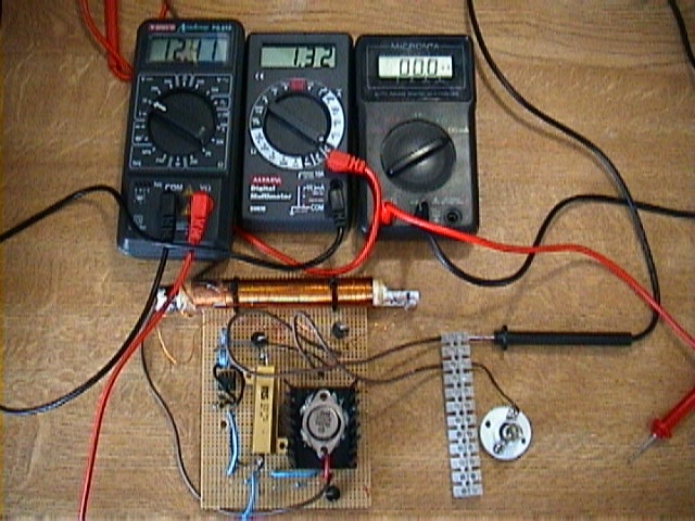
The current drawn from the circuit when it is not under load is 1.32Amps, but when the load (light bulb) is connected to the circuit the bulb glows bright, but the current drawn from the battery does not go up, infact the current drawn by the circuit actually drops.
This is the circuit without a load. The left meter reads battery voltage, the middle meter is current drawn from battery and the right meter is load current.
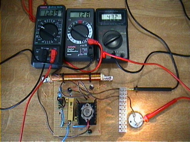
This picture shows the circuit under load. The current drawn drops to 1.28amps from 1.32amps.
Test Results 30/04/00
Today I have tested the circuit with a DC motor. The motor draws 800mA, but the current from the battery now drops by 500mA. At the moment it seems the more current you try to draw from the circuit, the less current is taken from the battery.
The Main Principle of the TEP - Courtesy J Naudin
Click here to see the original info
The main purpose of the TEP device is to act as a Time Energy Pump Vs ZPE ( Zero Point Energy )
You will find bellow some guide lines of the TEP concept.
The main principle of the TEP device may be decomposed as this :
- Using the parametric effect in a bifilar coil as an energy pump. When the circuit is closed on the Bifilar coil, the inductance drops rapidly near zero and the energy stored in the coil increases dramatically. During this energy growth in the TEP, I think that a kind of "siphon effect" must act in the TEP coils Vs ZPE (Zero Point Energy). This "siphon effect" will tap additional ZPE energy like a vacuum pump using water.
The additional energy tapped in the ZPE ( with the parametric effect in the TEP ) seems the only way to "regauge" the system and achieve an Overunity device.
Unlike a mechanical device ( the SMOT/RMOD device or an Overunity Magnetic motor ) which uses gravity or a little magnetic pulse to regauge itself, the TEP uses the parametric effect as a "siphon" Vs ZPE to regauge itself.
The disruption effect due to the parametric effect in the bifilar modifies the time constant of the circuit (L/R), thus the energy flows. The dissymmetry between the S-Flow (Poynting flow) running outside and the Time Flow compression inside the circuit (time constant compression) is the main cause of the Pumping effect in the ZPE. Today, I think that the TEP is "a way" to achieve a good Overunity device.
Today the TEP uses bifilar coils technologies in parametric conditions, but tomorrow, other kinds of process could be used to pump the Zero Point Energy. The only purpose of the TEP device is the creation of a dissymmetrical flow of energy between the outside flow energy (Poynting S-Flow) and the inside ( current flow in the wires ) during the energy flow from Source to Load and I think, today, that it is a good way to Free Energy.
The main advantage of the TEP is that it is a solid state device with no moving parts.
There is a great number of regauging steps due to the working frequency, thus the ZPE energy tapped may be enormous.
Sincerely,
Jean-Louis Naudin ( France / GMT+2 )