|
Time Travel Research Center
© 2005 Cetin BAL - GSM:+90 05366063183 -Turkey/Denizli
last updated
on: May 15, 2004
Report on the
StarDrive Generator Proof-of-Concept Experiment
* * * * * Introduction:
As those who have been following Archer Enterprises'
StarDrive Engineering Project news updates already know, we
recently built and tested a full-scale experimental mock-up of our
over-unity 24kW StarDrive (EDF) Generator's
primary power system. Over-unity engineering enthusiasts should be
very pleased and excited to learn that the in-house testing we've
now completed indicates our first-stage proof-of-concept
experiment was a qualified but extremely encouraging success!
This report will endeavor to document and interpret our verified
experimental results and their bearing on the 24kW
prototype of the exotic Electrodynamic Field Generator that has such
enormous potential to effect a radical reduction in the net cost of
producing electric power.
It must be noted that this first-stage PoC experiment was
not intended to demonstrate the over-unity operation of a
complete electrical circuit or device, which we can do only with a
full prototype that will be very expensive to construct – much to
the disappointment of certain potential investors who've contacted
us looking for a cheap 'sure thing'! Accordingly, the experiment was
not intended to model the construction or operation of the Field
Induction System, which basically constitutes the "other half" of
the EDF Generator electrically – but whose operating theory is
really not in question and whose performance is subject only to
component manufacturers meeting affirmed specifications.
Synopsis:
What the PoC experiment has established are the two
crucial features of the EDF Generator which are necessary to
enable its over-unity operation: (1) that brushless
electrostatic induction means can be used to fully-energize the low-resistance/high-ampacity
rotor with negligible input electric power, while at the same
time effectively isolating the input circuit from the device's
output load current (or any magnetic losses associated therewith!);
and (2) that a net positive voltage will be induced on the rotor's
primary anode rings which is sufficient to excite the Primary Arrays
that establish the Field Induction System's output circuit current.
[It's suggested that the reader become familiar with the
updated
Method of
Operation Summary page (unless previously reviewed) before
proceeding to the Description section below.]
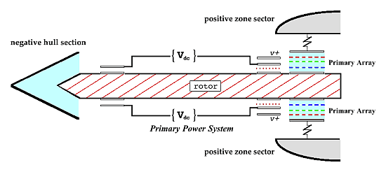 |
Description of the Experiment:
This experiment is actually very simple in the mechanical
sense, being comprised of only three (3) main components: two
stationary induction ring mounting plates and a non-dynamic 'rotor'
assembly "sandwiched" therebetween. The induction ring plates are
positioned plane-parallel to the rotor in a mutually opposed
configuration, as seen in the diagram above, and together with a
source of fairly high DC voltage they
constitute the EDF Generator's Primary
Power System. The Primary Arrays shown above are uniform
circular arrangements of modular thermionic electron source
assemblies, comprised of cylindrical heaters, rod-shaped resistors,
wafer cathodes, and screen-mesh control grids. In the full prototype
Generator, these Field Induction System components will be designed
and built to our specifications in association with a selected
outside vendor – and represent nearly 'off-the-shelf' components in
some cases.
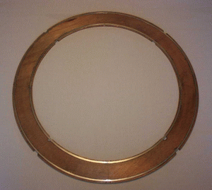
The photo at right shows one of the two identical
induction ring mounting plates. Each
plate was actually cut from 1/4" plywood and sealed with several
heavy coats of shellac. The induction rings are thin stainless steel,
precision cut by laser so that they each have exactly the same
surface area. A negative voltage will be applied to the 'smaller'
inner ring, whereas the outer ring will be positively charged. Once
the mounting plates were scribed for absolute ring concentricity,
the rings were affixed with a thin uniform layer of epoxy. The edges
of the rings were also sealed with the dielectric adhesive, to
minimize undesirable electric field leakage.
The next photograph shows one of the two
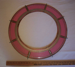 identical faces of the rotor assembly
mock-up, with corresponding induction rings and 'extra' primary
anode ring affixed. All three rings on each rotor face are
conductively linked by 8 underlying radial stainless steel segments.
The voltage induced on the matched outer pairs of rotor rings will
be the opposite of that applied to the 2 induction rings on
each plane-parallel plate. A positive voltage should appear on the
induction rings which enclose the anode rings, and thus on each
anode ring itself. The value of the induced anode ring voltage
depends not on the applied induction ring voltage but on the
magnitude of the field intensity achieved in the gaps between the 4
plate-and-rotor ring pairs.
identical faces of the rotor assembly
mock-up, with corresponding induction rings and 'extra' primary
anode ring affixed. All three rings on each rotor face are
conductively linked by 8 underlying radial stainless steel segments.
The voltage induced on the matched outer pairs of rotor rings will
be the opposite of that applied to the 2 induction rings on
each plane-parallel plate. A positive voltage should appear on the
induction rings which enclose the anode rings, and thus on each
anode ring itself. The value of the induced anode ring voltage
depends not on the applied induction ring voltage but on the
magnitude of the field intensity achieved in the gaps between the 4
plate-and-rotor ring pairs.
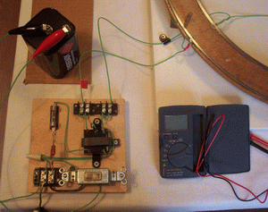
This next photo shows the lower induction ring plate mounted to
a solid wood base, using dowel rods in a 'post-and-hole' system,
with its solid-state DC-DC
converter voltage source circuit (shown center-right on the
small square board). Given input of 1-12 volts+, the source will
yield a proportional output to + or – 1,000
volts or to + and – 500 volts when a center
tap is grounded. [Peak input power < 3.0 watts.] A 56-ohm
input resistor and 1/4-amp fast-blo fuse were used to guarantee
voltage source protection in the event of output circuit arcing.
The last photograph of the series shows the
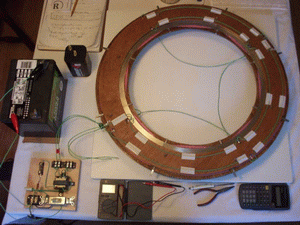 entire
test set-up, with an initial dual plate-to-rotor gap of
0.018". This results in a peak gap field intensity of 42% of vacuum
breakdown intensity at the typical applied ring voltages of +
and – 288 volts (as will be discussed further below). Since
the induction rings were all cut in four 90o
arc-sections, the wires that can be seen in the center of the set-up
and taped to the back of the upper plate are jumpers used to insure
uniformity of applied ring voltages. A second series of tests was
done with gapping of 0.010", for a peak gap intensity at 76% of
vacuum breakdown [Ebrk = 76,200
V/in.]. entire
test set-up, with an initial dual plate-to-rotor gap of
0.018". This results in a peak gap field intensity of 42% of vacuum
breakdown intensity at the typical applied ring voltages of +
and – 288 volts (as will be discussed further below). Since
the induction rings were all cut in four 90o
arc-sections, the wires that can be seen in the center of the set-up
and taped to the back of the upper plate are jumpers used to insure
uniformity of applied ring voltages. A second series of tests was
done with gapping of 0.010", for a peak gap intensity at 76% of
vacuum breakdown [Ebrk = 76,200
V/in.].
Experimental Results:
Although a great number of individual tests were done, the
following specific examples are most representative of the
progression of the experiment and the results obtained. It should be
pointed out that the DC-DC converter used in
this experiment serves the purpose and function of the toroidal
rotor-mounted field coils, whose nominal output voltage is
+/–319vdc in the 24kW
design prototype. By comparison, the highest applied induction ring
voltage recorded below was 91.7% of that value.
Test #1: [using 6-volt battery shown in the voltage
supply photo above; gapping = 0.018"]
- battery open-terminal voltage: +5.92
- net converter input voltage: +3.89
- resistor/fuse voltage drop: 2.03 [series current I =
V/R = 2.03/(55.9 + 2.9) = 0.035 amp]
- net converter power expended: 0.136 W [P = VI =
(3.89)(0.035) = 0.136 W]
- converter output voltage: +/– 136.6 [both inner and
outer induction rings connected]
- measured anode ring voltage: +2.421
> Observations: For the
operation of the rotor circuit to be "ideal", the matched plate-rotor
ring pairs must be perfectly plane-parallel and concentric, have a
gap field intensity in vacuum that's only marginally less
than the breakdown value, have no ring edge electric leakage flux,
and carry an arbitrarily small but finite gap conduction current. In
such a case, our mathematical model suggests that the peak anode
ring voltage induced could ideally approach 1/3 of the total applied
field coil (or voltage source) potential difference, because of the
rotor circuit's particular dual capacitive geometry. Obviously it
was not strictly possible in this experiment even to ensure
that any given one of the preceding criteria was met. And, in this
first test, the ratio of the induced anode ring voltage to the peak
theoretical potential difference is only 2.66% [2(136.6)/3 =
91.067, and 2.421/91.067 = 2.66%]
>>
Conclusions: The basic design of the power system (rotor)
circuit is fundamentally proper, in that the primary objective of
developing a net positive anode ring voltage is achieved (despite
the equal and opposite applied induction ring voltages). However,
the anode ring voltage induced was markedly lower than we'd hoped,
due to induction ring charge leakage from operation in air and the
unavoidably imprecise nature of the hand-built test set-up.
Test #2: [using the 12-volt battery shown in the
test set-up photo above; gapping = 0.018"]
- battery open-terminal voltage: +12.11
- net converter input voltage: +8.57
- resistor/fuse voltage drop: 3.54 [series current I =
V/R = 3.54/(55.9 + 2.9) = 0.060 amp]
- net converter power expended: 0.516 W [P = VI =
(8.57)(0.060) = 0.516 W]
- converter output voltage: +288.7 [this test done w/
neg. inner induction rings unconnected]
- measured anode ring voltage: +2.118
> Observations: Even
though the converter output voltage was more than doubled in this
test, the net anode ring voltage achieved with the negative inner
inductions rings unconnected was about 12.5% lower than in the
previous low-voltage test. Nearly 4 times the converter power was
required, as well, although consumption was still virtually
negligible (at 0.516 W). It's interesting to note that we are in
effect using an applied positive voltage to induce a positive anode
ring charge! While this may seem counterintuitive to the rule that
only unlike charges may be induced electrostatically, it must
be remembered that the mobile electron charge which is responsible
for the positive charge left on the anode rings is segregated as a
negative surface charge on the outer rotor rings. In this test, the
ratio of induced anode ring voltage to peak potential difference is
merely 1.10% [2(288.7)/3 = 192.47, and 2.118/192.47 = 1.10%]
>>
Conclusions: The primary power system as it's configured
seems at least twice (2x) as effective at pulling a positive anode
voltage with voltage applied to both inner and outer induction rings
than it is with the inner rings unconnected. It should be noted that
in additional testing done with the outer induction rings
unconnected, we found obversely that the system was much less
effective at producing anode ring voltage which in that case was
negative. It must also be pointed out that without both inner
and outer rings connected, the voltage-source-and rings combination
does not constitute a true rotor circuit as it would with two field
coils connected to induction rings at each end – the rotor is only
energized (either negatively or positively) and is not yet a
polarized 'source' like a battery, as will be discussed further
below.
Test #3: [using the 12-volt battery; gapping =
0.018"]
- battery open-terminal voltage: +12.41
- net converter input voltage: +8.70
- resistor/fuse voltage drop: 3.71 [series current I =
V/R = 3.71/(55.9 + 2.9) = 0.063 amp]
- net converter power expended: 0.549 W [P = VI =
(8.70)(0.063) = 0.549 W]
- converter output voltage: +/– 292.5 [both inner and
outer induction rings connected]
- measured anode ring voltage: +5.681
> Observations: We can see
in this test that the anode ring voltage achieved is significantly
more than double the value from the preceding test, even adjusting
for the higher converter output voltage (due to charging of the
battery), although only marginally more converter power was required.
In this Test #3, the ratio of the induced anode ring voltage to peak
theoretical potential difference is 2.91% [2(292.5)/3 =
195.0, and 5.681/195.0 = 2.91%].
>>
Conclusions: The inner pair of induction rings are
significantly more effective at pulling a positive anode voltage
than the outer pair, which would seem empirically reasonable given
their relative proximity to the anode rings, provided the
positive outer rings are connected. By comparing the ideal anode-to-source
voltage ratio (developed above) for Test #1 and this Test #3, we can
see that a higher applied induction ring voltage is more 'efficient'
at pulling anode voltage than a lower value at a given gap setting.
Test #4: [using the 12-volt battery; gapping =
0.010"]
- battery open-terminal voltage: +12.26
- net converter input voltage: +8.51
- resistor/fuse voltage drop: 3.75 [series current I =
V/R = 3.75/(55.9 + 2.9) = 0.064 amp]
- net converter power expended: 0.543 W [P = VI =
(8.51)(0.064) = 0.543 W]
- converter output voltage: +286.5 [this test done w/
neg. inner induction rings unconnected]
- measured anode ring voltage: +5.362
> Observations: The anode
voltage achieved in this test without the inner (neg.) induction
rings connected is significantly lower than that in the
preceding test, despite the 180% greater gap field intensity in the
energized outer ring pairs. However, this anode voltage is 2.51
times higher than in the similarly-connected Test #2 above, even
after adjusting for the difference in converter output voltage. It
can also be seen that the 'effectiveness' of induction has improved
in this test compared to Test #2, since the ideal anode-to-source
voltage ratio has in this case improved to 2.81% [2(286.5)/3
= 191.0, and 5.362/191.0 = 2.81%]. Not surprisingly, this increase
is by a factor of just over 2.5 times.
>>
Conclusions: Even though (once again) it might seem
counterintuitive by classical electrostatic theory, the observations
above show that the performance of the power system's
induction rings does not change in strict linear fashion with
decreasing rotor gap setting. [field intensity E = voltage
V ÷ distance d.] This clearly indicates that for
best performance (in anode ring voltage induction), the dual gap
setting should be absolutely minimized – since the anode voltage
should in practice be maximized to an extent.
Test #5: [using the 12-volt battery; gapping =
0.010"]
- battery open-terminal voltage: +12.26
- net converter input voltage: +8.37
- resistor/fuse voltage drop: 3.89 [series current I =
V/R = 3.89/(55.9 + 2.9) = 0.066 amp]
- net converter power expended: 0.554 W [P = VI =
(8.37)(0.066) = 0.554 W]
- converter output voltage: +/– 284.7 [both inner and
outer induction rings connected]
- measured anode ring voltage: +10.641
> Observations: In this
last test, the anode ring voltage achieved with both inner and outer
induction rings connected is essentially double the value obtained
in the preceding test, as it should be, although as before in the
similar case the converter power expended (~1/2 watt) increased only
marginally. Also as expected, the ideal anode-to-source voltage
ratio has in this case doubled to 5.61% [2(284.7)/3 = 189.8,
and 10.641/189.8 = 5.61%]. At this point, we began experiencing
various ring-to-rotor localized shorting phenomena with the test
set-up, due to problems associated with nonuniformity of the gapping
and operation in air during warm and humid conditions. When the set-up's
dual rotor gap was carefully realigned as accurately as possible to
a uniform 0.010", the best anode voltage achieved (in cool dry
conditions) was actually +16.44 volts.
>>>
Conclusions: From the preceding observations and conclusions,
both the validity of the ideal design parameters cited earlier and
the logical course of research and development to improve Primary
Power System performance are plainly indicated. While the anode ring
voltage induced was markedly lower than we'd hoped, due to charge
leakage from operation in air and the unavoidably imprecise nature
of the hand-built test set-up, it also clearly shows (as discussed
below) that in final practice we can achieve Field Induction
System operating conditions in the EDF Generator which are
comparable to those in the pentode vacuum tubes upon which the
design of the device's Primary Arrays is based. Unlike in a typical
pentode tube, however, the primary cathode heaters will again
require negligible input power once the "run" no-load housing
circuit current is established through the power resistors, due to
internal heating, and this is the very feature which will ultimately
support over-unity operation in this device.
Discussion:
Given that the 72 modular thermionic electron source assemblies
of the Field Induction System will function essentially like vacuum
tubes in operation, and be 'powered' by the anode ring voltage, the
+16.44 peak test anode voltage cited above becomes an important
supporting datum for proof-of-concept in this first-stage experiment.
While most vacuum tubes which have at least one grid are designed to
operate at anode voltages in three figures, a whole class of pentode
tubes exists that use an anode voltage of only +12.6.
Provided the rotor is properly polarized by the addition of a pair
of ballast capacitor rings that are mounted at the rotor's
periphery, and these outermost rings are arranged so they may gap-discharge
to the housing's emitter ring, the internal portion of the Field
Induction System circuit will be completed by the rotor. Given
heated-cathode sub-assemblies which meet the operating specs
affirmed by the maufacturer, it is then virtually certain that the
Primary Arrays can initiate and sustain full-load output Field
current.
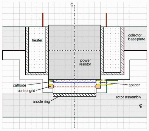
The diagram above shows a
modular primary array assembly in cross section. The stub heater
indicated draws full-load power of about 40 watts, while bringing
the power resistor and its affixed cathode to their orange-heat
operating temperature. Interestingly enough, the no-load 'run' Field
current in an EDF Generator equals the full-load current it will
also carry in operation, and the Field current voltage drop across
all of the resistors provides the AC inverter input power. Since the
24 kW Generator's small DC drive motor will
only require about 120 watts maximum power, peak input power for the
device will be 72(40) + 120 = 3,000W. With
peak output power of 24 kW, the minimum
COP will equal (24 – 3) / 3 = 7.0. And since the power
resistors must each be largely if not entirely self-heating
in operation, due to 333W of internal heating
from their high resistivity, our optimism that in practice a COP of
20 can realistically be achieved is understandably explained.
Polarization of the Rotor: Polarizing the EDF
Generator's rotor electrostatically, whereby it acquires an induced
negative voltage about the outer periphery and a positive voltage at
its inner circumference, requires that ballast capacitors be used
whose inside 'plates' are connected to the rotor segments (just
outside the largest ring shown in the 2nd test photo) and whose
net negative charge storage capacity is carefully chosen
according to somewhat complex considerations. The role these very
key components play in properly integrating the Primary Power System
with the Field Induction System output circuit is described in the
attached 1-page
Technical Overview.
Ballast Capacitors: It's important to note that these
capacitors will distribute electron current to the housing emitter
ring only once their induced negative plate potential is sufficient
to cause breakdown field intensity across the segment tip emitter-to-housing
chamber gap. Without the Primary Arrays 'connected' to complete the
Field Induction System circuit and enable the rotor assembly to
acquire a net negative peripheral charge, the capacitors'
saturation charge must be drawn in proportional measure from the
anode rings – which will therefore present a substantially elevated
positive voltage.
Second-Stage PoC Exeperiment: A 'second-stage' proof-of-concept
experiment is planned which will incorporate suitable ballast
capacitors and which will utilize machinable ceramic mounting plates
and rotor subassembly (to further optimize the test results obtained
and the production specifications derived) We anticipate being able
to develop anode voltages of +18-20 with this next test set-up (with
the ballast capacitors unconnected), to demonstrate and measure the
anode ring "boost" effect just described, and finally to prove that
true source polarization of the high-ampacity rotor assembly is
achievable with the present design.
The experimental testing described above was done with the
participation and supervision of Joseph Scott, M.Ed. [of Dundee, NY],
who can verify that the results obtained therein are legitimately
represented. Prof. Scott has extensive formal academic training in
physics.
* * * * *
to StarDrive home page to
Energy Systems page
H içbir
yazı/ resim izinsiz olarak kullanılamaz!! Telif hakları uyarınca
bu bir suçtur..! Tüm hakları Çetin BAL' a aittir. Kaynak gösterilmek şartıyla siteden
alıntı yapılabilir.
The Time Machine Project © 2005 Cetin BAL - GSM:+90 05366063183 -Turkiye/Denizli
Ana Sayfa /index /Roket bilimi / E-Mail /CetinBAL/Quantum Teleportation-2
Time Travel Technology /Ziyaretçi
Defteri /UFO Technology/Duyuru
Kuantum Teleportation /Kuantum Fizigi
/Uçaklar(Aeroplane)
New World Order(Macro Philosophy)
/Astronomy
|