last modified on: Mar. 25, 2005; see update below!
– the Faraday Disk Dynamo as the
original over-unity device –
[Note: Any updates made to this page will
involve no non-textual changes of any kind, to preserve the
integrity of the design models discussed in the Analysis sections
as valid reference material. The Tesla & Back-Torque Theory
feature section has been revised to include a more
accurate and complete discussion of eddy current and stator coupling
losses. Our thanks to the huge number of visitors this webpage receives,
and to the many students and engineers who have written us about the
report.]
Synopsis:
As many students, engineers, and over-unity researchers may already
know, it's very hard to find a single good Internet reference
resource which soundly assesses the early
Faraday induction dynamo in
comparison to a latter-day derivative – the "unipolar generator". Basic
engineering design information on either device is often inaccurate or
misleading, and sometimes erroneous.

Quite a number of determined
inventors and experimenters have attempted to develop a "formal" self-sustaining
over-unity variant of the disk dynamo which was 'unipolar' in that it
was statorless, but virtually none have ever succeeded.
The fact that a few have actually demonstrated a "free energy"
operational power gain is important to point out in this turbulent time,
when a definitive breakthrough in over-unity electrical power generation
is needed so imperatively and so few people are having any real success
at achieving one that is practical. Therefore, we are pleased to
offer this webpage as a concise but detailed engineering analysis of
these fascinating machines, one that appears to be much-needed, in order
to foster a proper understanding of them and to assist students and
alternative energy enthusiasts in their researches.
A Faraday dynamo or unipolar generator doesn't lend itself well to
practical commercial development because of the nature of its output,
since it produces very low (even fractional) DC voltage at extremely
high current. When Nikola Tesla invented polyphase alternating current
near the end of the 19th century, the concentrated development of DC
power systems based on Faraday's original work virtually ceased.
However, Faraday dynamos and generators are well-suited to easy
and precise mathematical modeling, both mechanically and electrically.
If we clearly show that formal* over-unity
operation can be achieved with this technology, it could be that
due cause is indicated for its renewed development – given recent
advances in solid-state DC-DC current conversion and regulation.
And while Michael Faraday's simple "new electrical machine" may not
really be suitable for commercial-scale power generation, as we will see,
it's quite possible that a stand-alone residential power plant
could be developed from it!
[ *Note: For our purposes here, we define a formal or self-sustaining
over-unity device as "an electrical machine or self-contained system
that, once started, will operate entirely on its own output and supply
excess power to a load with no external input energy being provided
thereafter by the operator." Thus, an
electrical device that operates over-unity is one wherein the
dynamic zero-point-energy environment contributes enough input energy
that the ratio of output to operator-input (
"coefficient of performance", or COP) is greater than 1.0.
Operator input is made, of course, in the form of applied torque.]
Introduction:
Before we make any detailed analyses of the Faraday disk
machines, it will be useful to briefly summarize their essential
mechanical and magnetic characteristics. The disk induction dynamo shown
below exemplifies the following form of Faraday's Law of Induction:
an electromotive force [emf, or voltage]
will be induced in any conductor that is moving across or "cutting"
magnetic flux lines, and the emf is proportional to the rate at which
the flux lines are being cut. Thus, the rotating disk cuts the
flux produced by the stationary magnet field pieces, and a voltage
appears between the inner and outer edges of the disk.
 |
correct interpretation of disk dynamo
action, as shown, whether field pieces are conductive or not.
Of course, we now know with a certainty that the rotor of
such a generator is subject to a magnetic back-torque that is
proportional to the output current drawn, due to the operation of Lenz's
Law, which states that: a current set up by an emf
induced due to the motion of a closed-circuit conductor will be in such
a direction that its magnetic field will oppose the motion causing the
emf. But, as it turns out, it is this same 'limiting' principle
which allows this device – and nearly all common rotating power
generation equipment – to also function as an electric motor: if
the appropriate voltage and current are supplied, in this case between
the center and edge of the conductive rotor, the disk will rotate with
about the same motor torque as it requires for a corresponding level of
generator action.
Curiously enough, shortly after Faraday's initial experiments
with a primitive version of the induction dynamo he discovered that
the same voltage could be induced if the
magnetic field pieces were affixed directly to the rotor, but that
no voltage at all would be induced if the field pieces were rotated
while the conductive disk was held stationary! He logically
inferred that even if the field pieces were rotating, their magnetic
fields must be stationary, and that the type of uniform magnetic
field produced by a cylindrical magnet must therefore be a property of
space itself (or perhaps more accurately, space-time) and was
independent of the magnetic material which serves to create the field.
This quality or effect is an oddity which to this day has no
satisfactory explanation.
 |
incorrect interpretation of
statorless generator action, promulgated by certain researchers.
Some theorists mistakenly assumed that
a statorless "unipolar" generator (like that shown
above) can no longer also serve as a motor,
presumably because the magnetic field produced by an applied rotor
current can't 'properly' oppose that produced by field pieces which are
rotor-mounted, in "normal" accordance with Lenz's Law. The logical
inference then drawn by certain researchers, perhaps most notably
the late Bruce DePalma (a physics professor at MIT) and electrical
engineer Paramahamsa Tewari in India, was that a
statorless generator therefore would not exhibit the normal Lenz
losses [as back-torque] provided that the magnets used are
nonconductive – and so it should most assuredly be
capable of functioning at an over-unity level of output!
DePalma's explanation for this peculiarity was simply that the
interaction of the primary magnetic field with that produced by the
radial output current results in a shear torque between the
conductive disk and the field pieces which is resisted by mechanical
attachment, and so is wholly constrained within the rotor assembly
and not reflected back to the mechanical drive!
The experimental evidence seems to indicate that neither of these two
predicate assumptions is true, however, as we'll see.
DePalma's 'discovery' [circa 1977] that a unipolar generator's field
pieces should be nonconductive to avoid the production of magnetic back-torque
is illustrated by the "N-effect" diagram at left below – and could in
fact be arrived at through simple deductive reasoning. If a rotating
cylindrical magnet produces a stationary field, and the magnet itself is
conductive (e.g., Alnico), then a voltage should appear between the
center and outside surface by Faraday's Law of Induction! The trouble is
that the act of drawing any load current from such a set-up will once
again produce a classical level of back-torque, by Lenz's Law.
 |
|
 |
Why DePalma called the device of his design shown on the
right above an "N-machine" is something of a mystery, since it is in
essence merely a typical unipolar generator. It is also interesting to
note that although he has properly indicated the polarity of the induced
voltage in the N-effect drawing on the left – according to the
traditional left-hand rule** for generator action
– the polarity shown in the drawing on the right is incorrect! And, as
we've indicated in our preceding drawings, the
preferred and logical polarity for any DC disk generator device is that
whereby the negative terminal is located at the circumference
– so that any "Hooper-effect" electromechanical centrifuging of mobile
conduction electrons is series-aiding with respect to the induced
load current flow. [In this case, it's important to realize that pure
DC current has actual mechanical momentum, whereas AC current does
not!]
[ **The left-hand rule for generator action
is as follows: Extend the thumb, index finger, and center finger of the
left hand at right angles to one another, so that the index finger
points in the direction of the flux (north to south) and the thumb
points in the direction of the motion; the center finger will then point
in the direction of the induced electron flow (negative to positive).]
Review of Prior Art:
In an ongoing effort to develop a self-sustaining unipolar
generator system that just might be able to serve as a stand-alone
residential power plant, Bruce DePalma and his principal correspondent-collaborator
Paramahamsa Tewari built and tested very large, unwieldy, and expensive
apparatus in reliance on the inherent design scalability of the Faraday
machine. A number of perceived "improvements" over the basic technology
were also implemented, but the underlying logic with which these
changes were selected and made was perhaps inherently flawed – with
negative consequences for both the cost-effectiveness and the
coefficient of performance (COP) of the
equipment [examples of which may be seen at the DePalma
website (depalma.pair.com/index.html)
and at www.tewari.org.
The famous Kincheloe Report (1986) on the testing of one of
DePalma's larger N-machines may be reviewed at
www.totse.com/en/fringe/free_energy/dpalma5.html.
Despite the fact that DePalma made a number of questionable design
choices in the "Sunburst" device tested by Robert Kincheloe (Professor
Emeritus, Electrical Engineering, Stanford Univ.),
the data suggests that the back-torque losses were only about 20% of
generated power – instead of the classical >100%. Prof.
Kincheloe also states that: "while DePalma's [output] numbers were high,
his basic [free energy] premise has not been disproved"; and "there is
indeed a situation here whereby energy is being obtained from a
previously unknown and unexplained source."
These two pioneering experimenters and many others seem to
have made a primary assumption for which we have
so far found little supporting evidence: that a disk dynamo-motor
could be shaft-coupled to a unipolar generator, which in turn powered
it, to great advantage. It might then seem that even if
the dynamo-motor itself was not over-unity in nature, the external input
electrical power required could be substantially reduced since the two
devices have very similar [but difficult to match] voltage and current
characteristics. But an under-unity machine of the original
stator-and-rotor disk dynamo design would only be as efficient if used
as an electric motor as it was as a generator: its motor
efficiency would not significantly exceed that of today's best
electric drive equipment, and the increased rolling load would tend to
offset any "power gain factor" by requiring proportionally greater
operator input power and cost.
The question arises whether such a combination could become input
self-sustaining if an over-unity disk induction dynamo was
somehow designed and incorporated. And in fact, mathematical modeling
suggests that this might be possible, in that
the dynamo's power output goes up by the 4th
power of increases in the rotor radius while its input power
requirement goes up by the square thereof. However, in accordance
with the earlier-stated relative equivalence of motor/generator action
in almost all rotating electrical equipment, there is every empirical
reason for believing that such a Faraday "dynamoelectric" motor could
only produce as much torque as it requires as a generator under full
load. Therefore, even if a given disk dynamo was able to exhibit a full-load
COP of 2 (for example) when used as a generator to convert input torque
to output current, it would exhibit a COP of only 1/2 or
0.5 when used as a motor to convert full-load input current
into output torque!! Thus, piggybacking the two
Faraday machine variants on a common shaft, in hopes of "bootstrapping"
the dual device to a state of self-sustaining operation, would actually
tend to be self-defeating from a practical standpoint.
Finally, both DePalma and Tewari elected at some point to try
replacing the permanent magnet fields with externally-powered
electromagnetic coils, but then a special "test cabinet" source was
necessary to supply proper power to these field coils – in addition to
the grid power always required by the primary
drive motor! This had the minor advantage of making the unipolar
generator's DC output fully variable and reversible. However, a flat
coil or solenoid produces a nonuniform magnetic field whose flux density
falls off with increasing distance from its radial centerline, unlike
the uniform field established between facing permanent magnets. With the
addition of ferromagnetic cores, the relatively weaker fields of the
facing electromagnets could then be greatly augmented and homogenized –
and AC power output could even be achieved – but only at the expense of
proportionally increased eddy current (Lenz) losses [that could only be
minimized by using cores made of a very nonretentive field grade (~3% Si
or other low-carbon) steel alloy, such as C1010.]
Although the N-machine and Tewari's "Space Power Generator" have
been claimed to exhibit COPs approaching 3.0 (or more),
these devices were never made capable of self-sustaining
operation nor were they (of course) ever cost-effectively mass-produced
and marketed. And while Tewari maintains that the technology "is
indeed commercially viable and should be brought to the attention of the
general public", he notes that prospective manufacturers "do not see a
market for a low-voltage, high-current machine."
We feel that successfully bringing an over-unity induction
dynamo system to market may actually be achievable, and that
the secret to doing so is quite simple: use a back-to-basics 'systems
approach' to develop a very straightforward yet sophisticated design
which avoids all of the unnecessary pitfalls just cited, one which is
self-sustaining once started with standard
12vdc car batteries and whose DC output is made
inverter-ready using advanced solid-state
current converters for output voltage pre-amplification. In keeping
with this strategy, we will investigate a feasible design for a product
that would hopefully be home-owner affordable
(using off-the-shelf or non-exotic materials and components whenever
possible) and compact (where the
unit's bulk size has been minimized while its output-to-weight ratio has
been absolutely optimized). The design theory we will examine and
develop below clearly sugggests that, under properly controlled
conditions, this is possible; it could turn out, however, that the
system as a whole might not yet be cost-effective under
'normal' circumstances . . .
Tesla and Back-Torque
Theory: There's ample
evidence to support both the view that back-torque will be produced in
any Faraday disk machine and the claim that
'drag' may be artfully reduced to much less than a
classically-figured level. Oddly enough, the notion that rotor
back-torque might not be produced in one type of Faraday machine or
another can probably be traced back to Nikola Tesla – and an obscure
1891 paper entitled "
Notes on a Unipolar Generator".
Taken out of context, Tesla's bald statement that "such a machine
differs from ordinary dynamos in that there is no reaction between
armature and field" was perhaps misconstrued as an absolute in the
case of the statorless variant: little
was known about it, since no one could otherwise see any good
reason to rotate the extra mass of the field pieces, and everyone
knew that back-torque was normally produced in a typical fixed-stator
dynamo.
[Significantly, perhaps, Tesla makes no
mention whatever of the statorless Faraday generator variant in this
paper. It should also be clarified that while some people may refer to
such a statorless homopolar machine as a "unipolar" generator, it's more
correct to let the latter term signify – as it did for Tesla – that
such an acyclic-voltage device produces pure DC current having only one
constant polarity (as in a battery), whether or not the field pieces
are stationary.]
However, careful review of the paper reveals that Tesla was
referring specifically to the case where we "assume
the current [is] to be taken off . . . by contacts uniformly
from all points of the periphery of the disc." His analysis
suggests that when a load current is drawn, eddy currents
will be confined to those radial sectors of the disk which do not lie
directly between the shaft and an outer pickup brush. In other words:
regardless of whether we rotate the field pieces or not, or whether
they're conductive or not, if we collected the
load current from a continuous peripheral brush which enclosed the
entire edge of the disk, no rotor eddy currents could be generated and
the 'normal' level of counter-torque would not be present.
[Its heavy eddy currents are of course a well-known major component of a
typical disk dynamo's total magnetic losses.]
What Tesla is really saying, then, is that the
more uniformly a disk dynamo's output current is drawn through the
periphery of the disk, the less "armature reaction" can be supported by
eddy currents within the disk – which are induced by the
stator magnets and therefore attracted to them. [This could also be seen
to validate the earlier contention that a disk machine whose output had
been sufficiently optimized to allow it to function as an over-unity
generator would constitute a proportionally under-unity motor!]
[Note: We can further show that no significant reduction of the
Lenz losses expressed in a disk dynamo can be made, even with ideal
stator shielding, until the angular width of the primary (radial
conduction) "brush sectors" – which is equal to the width of each pickup
brush – exceeds that of the adjacent ‘neutral’ (transverse deflection) "eddy
current sectors". Of course, the potential value of a practical liquid
metal brush system which provided 100% rotor disk edge 'coverage' is
also apparent – in that such a dynamo’s Lenz losses could
theoretically then be entirely eliminated when ideal stator
shielding is also employed – and is no doubt the reason why the U.S.
Navy imposed secrecy and gag orders on inventor Adam Trombly.
It's very important to realize at this point that Lenz
losses in a fixed-stator disk dynamo may take two (2) forms:
eddy current coupling, and stator inductive coupling. In
the first case, a full classical level of rotor counter-torque will tend
to be produced due to the attractive magnetic drag or 'friction' caused
by direct polar coupling between the applied stator field and induced
microcirculatory rotor eddy currents.
As it turns out, though, a full classical measure of similar
Lenz losses may also be produced by the stator, as a result of
simple attractive polar coupling between the net rotor magnetic
field [as expressed by "uncompensated" or asymmetrically-balanced
primary load current distribution] and any (i) exposed (unshielded)
outer stator magnet poles or (ii) incompletely field-piece-saturated
stator shielding.
[Note: An "ideal stator
shielding design" is one wherein the field piece assemblies exhibit
no external magnetic field outside of the flux gap (as in the "closed-path"
configuration developed by Adam Trombly.]
Thus, to the extent that stator coupling occurs, it will act
to produce additional magnetic drag upon the rotor which is
linearly proportional to the load current drawn - and thereby to satisfy
"Lenz’s Law". We may further infer that, even with perfect (ideal)
stator shielding to prevent any load current inductive coupling, a
fully-proportional Lenz-loss eddy current counter-torque load
will still seek to develop, to the extent possible (or allowed)
unless the rotor disk is highly sectored with pickup brushes.
[The percentage of 'normal' eddy current losses that any particular
disk dynamo will exhibit is a very complex function of its geometry and
that of its collector brush system. However, we have developed a
viable proper method for actually calculating the reduced eddy
current back-torque ratio that any given design should exhibit.
Interested persons may obtain a copy of our definitive
Eddy Current & Stator Loss Analysis
white paper upon request, with prior submission of a simple 1-pg. NDA.]
We can arrive at a new and much clearer picture of the nature of
reactive stator losses in this device, by means of the
following unbroken chain of logic:
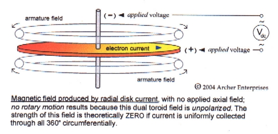
– (i) The magnetic field produced by
any disk rotor current(s) must rotate with the motion of the disk,
being in opposition to the stationary field(s) applied by permanent
magnets, or no motor action would result with an applied input current (instead
of applying torque); and
– (ii) this rotor current field must fully
enclose the disk without intersecting it, or it would act either
to generate a "free" voltage or to influence the disk's own inertia (neither
of which can occur, classically).
– (iii) Ordinarily, in the absence of an applied axial field, the
rotor current field would then take up a simple symmetrical dual
toroidal configuration (above and below the rotor plane) because of the
disk's radial geometry. But in this case, it must establish the
attenuated field configuration that's shown in the diagram on the right
below, because flux lines never cross – and those
of the rotating current field can't intersect those comprising the
stationary axial applied field (in which nearly all of the disk
is immersed).
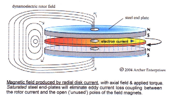
– (iv) Moreover, it can be seen that the rotor current field
completely encloses not only the disk but the applied stationary
fields as well. Therefore, the disk's rotating
current field may inductively couple to any ferromagnetic material on or
near the field pieces, which can thereby cause the stationary
applied field to impart additional armature reaction (or back-torque) to
the rotor, unless that material is magnetically saturated due
solely to induction by the field pieces.
– (v) Toroidal fields exhibit an inherently unfixed "radial polar
tendency", and will polarize attractively to any applied axial polar
field when radial torque is applied to them. Thus,
any extant net rotor field due to
self-generated current(s) will experience 'drag' against the
stationary applied field, regardless of its own polarity (and
disk current flow direction), as classically it must. In practice,
end-pole keeper plates can be used to nearly eliminate any magnetic
interaction between induced rotor current and the field pieces
themselves – even if they're metallic and rotating.
– (vi) Most importantly, however, it can be shown by integral calculus
that the primary rotor current's net
magnetic field around the disk is inversely proportional to the
extent to which that current is drawn in opposite radial directions
(i.e., by pairs of 180o-spaced brushes), because the net load
current enclosed [by the path of integration] is then zero – due
to equal currents flowing in opposite directions – thereby
mathematically confirming the fundamental validity of Tesla's guiding
design principle!
Recalling now that a conductor must move relative to a
stationary field for voltage to be induced, we may also deduce the
following design first-principles: (1) to wit, the
primary rotor current field will not act to induce eddy currents
in metallic stator magnets, which in turn won't impose
corresponding additional back-torque (as Lenz losses); but (2)
however, when metallic magnets are used for the
applied field in a 'unipolar generator', there is relative
motion between a rotating conductor and a stationary field, so field
piece eddy currents will be induced which may couple to
the rotor field and contribute to back-torque!
Taken together, the preceding material clearly shows that – with
ideal stator shielding – back-torque will only
be expressed in an induction dynamo (with a fixed stator) to the
extent that eddy currents are allowed to circulate in "unused" radial
sectors of the disk*, and this principle can now be used to
figure what percentage of the classical eddy current back-torque will be
produced: it is simply (but not strictly) proportional to the
ratio of that portion of the disk's circumference which is not 'covered'
by its collector brushes to its entire circumference!
[Note: This presumes of course that the load current is shared
equally by uniformly-spaced pairs of oppositely-vectored brushes. Many
different brush system configurations are possible for any given size
dynamo; e.g., we will use a total of 64 brushes in the 'preferred
embodiment' 18"-dia. prototype we're building.]
This same reduced
back-torque ratio also applies, of course, to a 'unipolar'
generator. Unfortunately, it can also be seen why only the much-less-powerful
nonconductive (ceramic) magnets have generally been used in the
statorless variant, since induced field piece eddy
currents can transfer magnetic load to the rotor field in a
statorless generator if the magnets used are metallic –
because the load current's rotating magnetic field encloses the combined
stationary fields of the permanent magnets and tends to polarize
attractively to them. [An applied disk current's rotor field
would polarize repulsively, of course, resulting in motor action, in the
absence of an applied radial torque.]
Finally, in this regard, it could be said that
in a Faraday disk generator the motor field encloses the stator field,
and not the reverse – as almost universally is done in
common electromechanical practice. Perhaps the possibilities inherent in
this unusual arrangement are part of the mystery and fascination these
machines have always held for the engineering-inclined. And the greatest
"secret" of both these disk machines (as we see it) is that
it's possible in effect to trade the classical
Lenz loss back-torque for a much-smaller collector brush torque load
requirement [in the generator variants].
In any event, in the Analysis sections to follow, we will
calculate the input torque, output power, and efficiency (or
coefficient of performance ) of both an
induction dynamo and a unipolar generator of the same physical size,
for both the classical case and the adjusted theoretical model developed
from the refined design principles just discussed. It is then up to the
reader to empirically decide which results are the more accurate . .
.
Getting Back to Basics:
In this section, we'll concentrate on deriving some essential
formulas which properly govern and define the basic operating
characteristics of both the Faraday disk dynamo and its unipolar
generator variant (i.e., voltage, power, input torque, etc.). From these
simple equations, we will be able to develop some further sound
engineering guidelines and appropriate design first-principles.
Voltage:
While many texts will show calculus used to determine the
accepted generalized formula for induced voltage in the disk
machines, this relation is much easier to derive by simple algebraic
means from Faraday's own general rule of induction.
[a] To wit, the magnitude of the terminal voltage
induced in a conductor depends on three factors: (i) the flux density of
the applied field; (ii) the length of the conductor immersed in the
field; and (iii) the velocity at which the conductor moves through the
field. Taking the simple product of all three factors yields the
equation E = B l v ,
where E is in volts, B is the flux density in
tesla (or webers/m2
), length l is in meters, and v is the velocity in
m/sec.
[b] In a general sense, we may let length l
= r , where r is simply the full annular
width of the rotor (in meters). Then, we can let the average angular
speed of rotation v = (2π r f) / 2 ,
or v = π r f ,
where f is the rotor's frequency of rotation in revolutions per
second.
[c] Therefore, E =
output voltage Vo
= B r (π r f) .
And thus, nonrigorously, Vo
= π r2 f B .
[d] In reality, we must let the length
l = Ra , where Ra
is the radial width of the rotor's net working flux gap area (in meters).
Also, we'll let the average angular speed of rotation
v = 2π r f ,
where r now specifies the mean radius of the
flux gap area as measured from the rotor's axis, and f is the
rotor's frequency of rotation (in rps).
[e] Then, Vo =
B Ra (2π r f ) ;
and, merely rearranging terms,
Vo = 2πr Ra f B .
This formula will now yield the necessary accuracy of voltage
calculation, since that portion of the rotor disk which is actually
immersed in the field is properly indexed to as-specified dimensions for
the field pieces.
It is important to point out that Vo
as figured by the formula just derived can actually be treated as both
an open-terminal and full-load value. It can be shown
theoretically, and has been experimentally verified, that a disk dynamo
or generator's rotor charge will be distributed in such a way that its
output voltage is quite constant regardless of the load current drawn,
and these machines therefore behave as if they were a regulated voltage
source!
Resistance:
Having developed the relative radial planar-dimensional
relationships for the disk devices, so that we can properly project
operating voltage, it then becomes necessary to address the issues of
volume resistivity and internal rotor circuit resistance if we
wish to correctly figure the output current I (according
to V = I R )
and power P (according to P = V I )
for any given size machine. No other aspect of system design is more
crucial to optimizing output or more responsible for unrealistic
projections of system performance.
It's easy to see that open-terminal resistance of a disk dynamo or
generator has only one seemingly major component: the resistance
of at least one pair of brushes. In virtually all cases, the resistance
of the rotor disk itself is and should be entirely negligible, generally
being measured in only the single-digit micro-ohms. And, it's true,
proper brush design and material selection will
probably "make or break" the system's COP in most cases. However,
in addition to brush-and-rotor resistance there's another type of
resistive loss that is sometimes not accounted for in design reckoning:
that of the microscopically-thin field discharge contact zone
between each brush and the rotor! This is actually the primary
resistance in all Faraday disk machines; it's largely responsible
for brush heating, and can be as much as 3 orders of magnitude larger
than the actual brush resistance.
It is essential in this technology to use the highest quality
brushes, having very high conductivity and a low coefficient of friction
(k). For silver-graphite brushes running on
silver slip rings or plated surfaces, static k is ~0.3 and
dynamic k is ~ 0.2. Each brush's contact interface resistance
in such case should not exceed 0.005 ohm initially and should
decrease to an average of Rz = ~
0.003 ohm after extended open-terminal run-in.
[a] The most convenient formula
for volumetric resistance is:
R = ρ L / A ,
where R is resistance in ohms; ρ is
the volume resistivity in ohm-cm; L is the length in the current
direction, in cm; and A is the current's cross-sectional area in
cm2. Appropriate use of this formula
to figure brush and rotor resistances will be illustrated in the
Analysis sections below.
Output Power: In most cases, voltage
can be thought of as the primary component of electrical power, as seen
in the relation given earlier above. Thus, to maximize the output power
Po of a disk dynamo or generator,
we absolutely must maximize the unavoidably tiny voltage it produces.
Not considering the required input power (and torque) for the moment, it
can easily be seen in the formula derived for output voltage (Vo)
that the most effective way to do this is simply to increase the rotor
radius – since a major measure of its radial width is factored in
twice.
At some point, however, the product of
increasing rotor size and speed will result in an unacceptably high
value for brush speed, and so the maximum OEM ft./min. rating of
the brush material selected will define an upper limit for the device's
output voltage and its rotating inertia. Of course, the flux
density B (as the final determining factor) can be maximized to
the extent permitted by the cost and availability of specialized
magnetic materials which have their own concrete natural field-strength
limits.
[a] From the two formulas
for power P given earlier above, it follows that
P = V (V / R)
= V2/ R .
Therefore, by substitution, the full-load output power
Po = (2πr Ra f B)2/ R .
Of course, if output current Io has
previously been calculated (since I = V / R),
Po is also conveniently equal to Io2R .
In principle, however, output power should only be based on the
calculated or measured value for Vo using
P = VI , due to the device's constant
voltage characteristic (as discussed above).
It should be noted that metallic neodymium iron boron magnets are
now available with flux densities approaching 1.4 tesla (or 14,000
gauss) This is the world's most powerful permanent magnet material. The
strongest nonconductive magnets generally available in large sizes are
made of sintered Ferrite 5 (BaO-6Fe2O3),
a ceramic material with residual flux density of 0.38 tesla (3,800
gauss).
Input Torque & Power:
Before we derive a generic formula for no-load mechanical
input power (in watts) that is strictly a function of a device's
rotating inertia and variable starting time, it is important to realize
that power P more fundamentally must reflect the brush and load
input torque T required, according to
Pi = 2π
f Ti
, and that torque is rotational force applied at a given distance from a
central axis of rotation. Torque may be expressed in newton-meters (N-m)
when the power is in watts. In the Analysis sections below, a
handy formula is provided for figuring applied induction motor torque in
foot-pounds (ft.-lb.) and rpm, in which case input power
will be in units of horsepower (Hp) [where 1 Hp = 746 watts].
In the induction dynamo, the primary load is the 'normal' generator
back-torque Ta, whose magnitude can be
simply computed (by virtue of Lenz's law) from the traditional equation
for the "force on a current element in a magnetic field":
F = B I
L , where for present
purposes I is equal to Io
(or the load current) and as before L = Ra
, where Ra is the radial width of
the flux gap area. The full-load back-torque due to induction may then
be found by using r once again to specify the mean radius
of the flux gap area in the standard relation for torque:
Ta = F
r , where F
will be a negative (retarding) value in N-m. [It is important to note
that: 1 N-m = 0.7376 ft.-lb. = 8.851 in.-lb.]
In an ideal disk generator, the primary load is just the
dynamic friction of the brushes, although an OEM-provided value for
static ('starting') coefficient of friction must
be considered. Of course, this will be a
substantial source of retarding torque and secondary load in any
practical disk induction machine. Recommended
values for spring pressure vs. material will
allow the total brush 'drag' to be accurately computed. The
negative brush(es) will contact the rotor disk's outer edge in the
design analyses we'll study below, so the full 'nominal' rotor radius
Ro will be used to figure outer brush
speed and resultant counter-torque. For simplicity, we'll consider the
positive brush(es) as running directly on a conductive rotor shaft (as
shown in the drawings above). The net forward force required to keep the
brushes from decelerating the rotor is:
F = p k A ,
where F is in pounds, p is spring
pressure in psi, k = coeffic. of friction, and A = total
contact area in square inches. [OEM-suggested
minimum spring pressure for silver-graphite brushes is 4 psi.]
[a] No-load
mechanical power to the rotor assembly is equal to the kinetic energy
stored therein at a given constant operating speed divided by the
elapsed time needed to achieve that speed: So, Pr
= Ek / t
. Ek is in turn equal to half the product
of the rotor's moment of inertia (I) and the square of its final "run"
angular velocity (ω, in
radians/sec), where ω = 2πf
: Pr
= [(½mRo2)(4π2f
2/ 2)]
/ t . And thus,
Pr = mπ2R2f
2 /
ts
, where Pr is in watts, m is
mass in kg, R in this case is the 'equivalent annular inertial
radius' [(A/π)1/2]
of the disk* (as figured below), and ts
is "start" time in seconds.
* [It is acceptable in this case to ignore the trivial
inertial moments of the shaft and two disk mounting flanges.]
Finally, once we have verified a prospective drive motor's full-load
torque capability, we will use the simple power formula
ts = ωI
/ T to see
if start time ts is acceptable for
the type of motor selected. It may be of interest and value for students
to know the provenance of this formula, which is derived as follows:
ω = a t , where ω
= 2πf (with f in rps), a =
avg. angular acceleration, and t is the elapsed (or starting)
time in seconds; and T = I
a , where T = avg. torque, and
I is the moment of inertia. And thus, t =
ω / a = ω
/ (T /
I), whereby ts
= ω I /
T .
Induction Dynamo Analysis:
In this first Design Analysis section, we will consider a disk
induction dynamo with a pure copper rotor 18" in diameter and
0.187" thick, which is mounted to a 1"-dia. dual-bearing
drive shaft made of a beryllium/copper alloy. The disk will be secured
to the shaft using press-fit CDA18135 (99%Cu;Cd/Cr) split flanges that
are silver-soldered to the disk and then set-screwed both to each other
and to the shaft. To allow for stator thickness, brush slip rings,
bearings, and drive coupling, the rotor shaft will be 8.5" in length.
Two field piece arrays, each composed of 173
NdFeB disk magnets that are 1" in diameter and ½" thick, will be
epoxy-resin-bonded into solid stator assemblies and mounted plane-parallel
to the rotor with a realistic mechanical clearance (in the flux gap) of
0.0085" on each side. Silver-graphite brushes
(93%Ag) will then be mounted
and connected as described above, with the matching rotor-edge and shaft
contact surfaces silver-plated.
 |
|
 |
Since multiple brushes will be absolutely necessary, the
outer brushes will be parallel-connected in sets of four (4) per inner
shaft brush, each separated by 90° of rotation – and more than one such
set may in turn be uniformly distributed around the rotor by equal 'sectoring'.
An even multi-pole number of such sets should be used, so that
the corresponding inner brushes may be installed uniformly on the rotor
shaft. The inner (shaft) brushes are assumed to be positive [see the
2nd following graphic].
Stator dimensions & flux density:
[i] flux gap outside radius OR = 8.2857" + ½"
= 8.7857"
[ii] flux gap inside radius IR = 2.2142" – ½"
= 1.7142"
[iii] flux gap radial width = OR – IR =
7.0715" = Ra = 0.180 m
[iv] mean induction radius = (OR + IR)/ 2
= 5.25" = r = 0.133 m
[v] net flux gap area = π(OR)2
– π(IR)2 = 233.26 sq.in.
[vi] total magnet area = 173 (0.7854)
= 135.87 sq.in.
[vii] gap area B-factor = (135.87 / 233.26)
= 0.5825 = 58.25%
[viii] disk magnet residual induction =
Br = 12,900
gauss
[ix] computed gap flux density* = 7378
gauss (see graph at right)
[x] net flux density = (0.5825)(7378
gauss) = B = 0.430 T
* flux density graph courtesy of Australian
Magnetic Solutions
Rotor mass & moment of inertia:
[i] disk density (pure Cu) = 0.323 lb./cu.in.
[ii] disk area A = π(Ro)2
– π(½")2 = 253.68 sq.in.
[iii] disk volume = (253.68)(0.187") = 47.44
cu.in.
[iv] wt. = (47.44)(0.323) = 15.323 lb., and
mass md = 6.965 kg
[v] equivalent inertial radius = (A /π)1/2
= 8.986 in. = 0.228 m
[vi] moment of inertia = ½(6.965)(0.228)2
= 0.181 kg-m2
Shaft mass & moment of inertia:
[i] density (Be/Cu alloy) = 0.302 lb./cu.in.
[ii] volume = 8.5 [π(½")2]
= 6.68 cu.in.
[iii] wt. = (6.68)(0.302) = 2.017 lb., and
mass ms = 0.917 kg
[iv] moment of inertia = ½(0.917)(0.0127
m)2 = 7.40 x 10⁻⁵ kg-m2
Now that we have developed the necessary physical data for an
18" dynamo model, we need only specify a few more operating parameters
before beginning a concise series of definitive performance calculations.
The magnets' residual induction (or Br)
has already been selected, and in this case is 12,900
gauss (1.29T) for standard grade-42 NdFeB disk magnets that have reasonable availability and
justifiable price. The flux gap distance is readily figured from
previous data, and is 0.204" or 5.2 mm. These criteria and the specified
magnet dimensions were used to generate the flux density calculator
graph provided above, from which the resultant gap flux density (quoted
above) was obtained.
Next, a rotation speed f must be
selected which is not only within the brushes' maximum rating but is
also hopefully at or very near an industry-standard electric motor speed.
Additional data (like brush spring pressure) will be furnished as needed
from OEM / vendor
recommendations and specifications.
Voltage:
For the brush material grade selected, the maximum suggested
contact speed is 5,000 fpm. While higher speeds are possible, brush wear
will become excessive in a continuous-duty application. Therefore, our
tentative design operating speed will be 850
rpm, with f = 14.167 rps,
using an 8-pole AC drive motor. This yields a comfortably-high
brush speed of 4,006 fpm. For comparison's sake, we'll also calculate a
peak output voltage based on a rotor speed of 1150 rpm (or 19.167
rps), using a 6-pole motor for a maximum brush speed of 5,419 fpm.
Therefore, at 850 rpm, Vo =
(6.283)(0.133)(0.180)(14.167)(0.430) = 0.9163
volts. And, at 1150 rpm, peak
Vo would equal 1.240
volts.
Resistance:
From the previous discussion of resistance, it should be
realized that we can quickly derive a theoretical baseline rotor circuit
resistance, and a corresponding maximum possible output current, by
ignoring the trivial disk, brush, and shaft resistances and considering
at first just the interface resistance of a set of 4 negative brushes
load-connected to one positive brush. The combined parallel
resistances of a couple even-numbered multiples of such brush sets can
then be easily figured, to provide a means of increasing the output
current. There will then be 1/4th as many positive brushes as negative
brushes, and for convenience we will consider the number of dynamo/generator
poles to be equal to the number of positive brushes.
For optimum performance, current must be drawn
from the rotor disk in as radially uniform a manner possible.
Therefore, the 2-pole (2-set) brush arrangement shown in the preceding
graphic is much better than the basic 1-pole (single-set) connection,
and a 4-pole connection having 4 separate 1-pole systems in parallel is
better yet. Based only on the ~0.003-ohm per-brush interface resistance,
these connection options result in the following minimum rotor circuit
resistances and corresponding maximum currents:
– in the 1-pole circuit, Rmin = 1
[(0.003 / 4) +
0.003] = 0.003750 ohm , and I
max = 244.35 amps;
– in the 2-pole circuit, Rmin = ½
[(0.003 / 4) +
0.003] = 0.001875 ohm , and I
max = 488.69 amps;
– in the 4-pole circuit, Rmin = ¼
[(0.003 / 4) +
0.003] = 0.000938 ohm , and I
max = 977.39 amps.
Obviously, it is decidedly to our advantage
to use the largest practical number of "pickup" brushes, although
extensive mathematical modeling suggests that the
total outer brush contact width should not be more than 50% of the
disk's circumference in a disk induction dynamo intended for use as a
motor. Accordingly, the brush current density rating
will serve to limit the number of outer brushes used and the maximum
possible current. The current density limit of the 93%Ag brushes we've
specified is 300 A/in2. In practice,
total brush ampacity should be strictly matched to the highest I
max figure derived that does not exceed the calculated safe
ampacity of the rotor disk (as discussed further below) and
total pickup brush width should be absolutely
maximized, approaching 100% of the disk's entire
circumference, in all generator (non-motoring)
variants.
All things considered, we will assume that the 4-pole/16-point
pickup brush circuit just described will be used in our 'prototype'
model and in the calculations to follow.
To get a better figure for our model dynamo's actual total
circuit resistance Rt, we will now
calculate the resistances of the brushes, rotor shaft, and disk.
Given the OEM specs for brush current density (300
A/sq.in.) and resistivity (2.0 x 10⁻⁶
ohm-cm), we may simply divide the value for I
max by 16 to find the ampacity of each negative (pickup)
brush and then divide the result by the current density limit to find
the contact area required. Therefore, the area of each outer brush An
= (977.39 / 16)
/ 300 = 0.2036 sq.in. or 1.314 cm2.
Outer brush thickness should be >
½ and < 2/3 of the disk thickness,
as the disk's outer edges should be slightly chamfered. So, the
width of each pickup brush will be 0.2036 /
0.125" = 1.63". The rotor's circumference is equal to 2πRo
= 56.55", the total pickup brush width is 16
(1.63) = 26.08", and so the edge-width 'coverage' ratio is 26.08 / 56.55
or 46% (which is nearly optimum for
a motor variant).
Using brushholders which are only 5/8" 'tall', a good minimum brush
length L is 1.0" or 2.54 cm. So, each pickup brush's resistance will be
(2.0 x 10⁻⁶)(2.54) /
1.314 = 3.866 x 10⁻⁶ ohm, or Rn
= ~ 4 μohm. Applying the same method to the 4
positive shaft brushes, with an assigned thickness of 0.50" the area Ap
= 4An = 0.8144 sq.in. (5.254 cm2)
and width again equals 1.63" or 4.14 cm. With length once again of 1.0",
each inner brush resistance Rp = ~ 1
μohm. Finally, it will be important in
practice to use the heaviest and shortest brush shunts (buss bar leads)
feasible.
The rotor shaft alloy that is greatly to be
preferred is CDA17200 1.9% beryllium copper, with volume resistivity of
7.733 x 10⁻⁶ ohm-cm but the highest
tensile strength of any copper-base alloy. To figure a liberal
resistance for the rotor shaft, we will allocate 5" or 12.7 cm as its "electrical"
length by mounting the positive brushes inboard of the bearings and
drive coupling. The axial end area of the shaft is equal to π(½")2
= 0.7854 sq.in. = 5.067 cm2, and the shaft resistance Rs
= ~ 19 μohm.
The rotor disk's greatest electrical resistance is expressed through
the edge of the 1"-diameter center shaft hole, the circumference of
which is 3.1416". Given a thickness of 0.187", this inner edge area then
equals 0.5875 sq.in. or 3.790 cm2. The volume resistivity of
pure copper is 1.724 x 10⁻⁶ ohm-cm,
and the disk's radial conduction length L is equal to Ro
– ½" = 8.5" = 0.216 m = 21.6 cm. Accordingly, we find the resulting
maximum possible rotor disk resistance Rd
= ~ 10 μohm.
Finally, we can now make the best possible projection of
the rotor circuit Rt in milli-ohms as
follows:
Rt = ¼ [(Rz
+ Rn) /
4 + (Rz + Rp
+ Rs + Rd)]
= ¼ [(3 + 0.004) /
4 + (3 + 0.001 + 0.019 + 0.010)]
= 3.781 / 4 = 0.945 m
ohm = Rt = 945 μohm.
Thus, it's conclusively demonstrated just how little effect the
electrical 'hardware' really has on the total rotor circuit resistance
of a Faraday disk dynamo (if properly designed), since the figure we
just derived with fair effort differs from the quick estimate we made
earlier by only 7 micro-ohms! Our revised figure for the
"nominal" output current is then equal to 0.9163
/ 0.000945 =
nom. Io = 969.6 A.
Output Power:
The output power of our model dynamo at the given nominal
rotation speed of 850 rpm (14.167 rps) is equal to I2R = Po
= 888 watts. But, at the 'peak' rotation speed of 1150 rpm (19.167
rps), the output power would be equal to V2/R = (1.24)2
/ 0.000945 = Ppeak
= 1,627 watts. It can therefore be seen that in raising the
operating speed by 1150 /
850 or 35.3%, the output current possible would rise to
peak Io
= 1,312 amps and the available power would nearly double! Of
course, every brush's contact area would also have to be
increased by 35.3%, and in the case of the outer brushes by increasing
the brush width to 2.02". Total pickup brush contact width then
increases to 35.29" or a reasonable 62.4% of disk circumference.
Unfortunately, it can be shown by rather involved numerical anlysis
of existing copper wire data that the safe ampacity of the 0.187"-thick
rotor disk is 'only' 1,129 amps around its inner circumference.
By increasing the shaft size to 1¼" the safe ampacity could be raised to
1,376 amps, thereby enabling the dynamo to be operated at its peak Io.
Rather than effect such a substantial device redesign, though, we will
continue our analysis on the assumption that the brush size and
operating speed shall be adjusted such that
max. Io =
1,129 amps.
Accordingly, the pickup brush width will have to be increased by
1,129 / 969.6 or 16.44% (to
1.90"). The total pickup brush width is 16(1.90) = 30.37", and so the
edge-width coverage ratio is 30.37/ 56.55 or
54%. The new value for
max. Vo = 1.067 volts,
and the corresponding maximum rotor speed is then
990 rpm or f = 16.497 rps. And so, the
maximum allowable output power is equal to (1.067)(1,129) or
max. Po
= 1,205 watts, and the new maximum brush speed is 4,665 fpm.
Input Torque &
Power: Although it might seem that we
now have good final figures for operating speed and output power, we
have yet to determine if the rotation speed we just derived is
acceptably close to that of an off-the-shelf electric motor (as a
practical source of input torque) which will provide adequate start and
run torque at a given available horsepower rating. This will not be
nearly as difficult as it might sound, with the aid of a simple yet
indispensable electric motor formula that relates speed (rpm), torque
(T), and power (Hp):
T = (Hp x 5252) /
(rpm) , where the constant 5252
is equal to 33,000 ft.lbs./min./Hp divided by 2π radians/rev., and T
is the torque in ft.lbs. [The equivalent metric expression is:
T = P /
ω , where ω = 2πf
, P is power in watts, and T is torque in N-m.]
For the 'classical' case:
[i] primary full-load counterforce = Fa
= B I Ra
= (.43)(1,129)(.180) = 87.39 N
[ii] primary back-torque = Ta = Fa
(r) = (87.39)(.133) = 11.62 N-m = 8.57 ft.lb.
[iii] neg. brush counterforce (ea.) = Fnb
= pkA = (4)(0.2)[.125 x (1.1644 x 1.63)] = 0.190 lb. (run)
[iv] pos. brush counterforce (ea.) = Fpb
= pkA = (4)(0.2)[(1.1644 x .500) x 1.63] = 0.759 lb. (run)
[v] total brush retarding torque = Tb =
16(Fnb)(Ro)
+ 4(Fpb)(½") = 28.88 in.lb. = 2.41 ft.lb.
[vi] total load torque T = Ta + Tb
= 8.58 + 2.41 = 10.98 ft.lb.
(treating the ~ 0.5% rolling losses as negligible).
Correctly matching a standard electric motor to the
mechanical load in this unusual application can be a complex and
challenging task. All things considered, there are
a number of reasons for selecting a permanent magnet or shunt-wound (wound
field) DC motor, since the required AC input converter (as
the power source) is usually also an economical variable speed
control. This feature is especially desirable in situations like the
present case, where our tentative operating speed falls right between
the 'standard' 1150 and 850 rpm motor speeds. Also, in certain cases
it may be inadvisable (although less expensive) to
use an AC capacitor-start motor in this application, since
they're designed to start under fully-loaded conditions and can
briefly draw over 300% of normal running amps to do so. [In an average-load
starting situation like the present case, this will also put a huge and
unnecessary strain on the rotor assembly, due to its large moment of
inertia.]
Referring to a motor selection and ordering guide (such as any
recent Grainger catalog), we find that a 2
Hp 1150 rpm PM motor (with 180vdc armature; FL amps = 9.8) is
available [GE 5CD125TP002B] that develops full-load
torque of 9.133 ft.lb. (109.6 in.lb.). Even though this is rather less
than the 10.98 ft.lb. that would be needed to operate our model dynamo
at its maximum capability, it must be remembered that (according
to the torque formula above) this motor's output torque will climb as
its speed is reduced – and it may be that just enough torque will be
available at or very near the maximum 990 rpm operating speed we desire.
The most straightforward way of determining that point on the
selected motor's output power /
torque curve where its operating speed is maximized for
this particular application's input torque requirement is by
repeated spreadsheet calculations to assemble tabular data, from which
the best 'solution' of such a complex covariable problem is obtained
when the net motor torque developed (Tm)
just exceeds the total load torque (Tn)
required at the reduced speed.
Starting at 985 rpm and figuring output voltages in
descending 5-rpm increments at first, the following optimal resolution
was found at 970 rpm (f =
16.167 rps):
– net Vo
= 1.0457 volts,
net Io
= 1,106.5 amps, and
net Po
= 1,157 watts
;
– net Fa =
B I Ra
= (.43)(1,106.5)(.180) = 85.643 N ;
– net Ta
= Fa(r) = (85.643)(.133) = 11.39 N-m =
8.40 ft.lb. ; and
– total load torque = Ta + Tb
= 8.40 + 2.41 = Tn
= 10.81 ft.lb.
[treating the ~ 0.5% rolling losses as
negligible].
– net motor torque developed = Tm
= (2 x 5252) / 970 =
10.83 ft.lb. > Tn (@
10.81 ft.lb.).
– nominal motor efficiency = (Hp x 746)
/ (V x I) = 1,492 /
1,764 = ~ 84.6%
– nominal dynamo efficiency = Po /
(Hp x 746) = 1,157 /
1,492 = ~ 77.5%
– combined system efficiency = (0.846)(0.775) = ~ 65.6%
– letting avg. brush k = ½ (0.3 +
0.2) = 0.25, avg.Tb
= (0.25 / 0.2)(2.41) =
3.01 ft.lb.
– avg. no-load motor torque Tnl
= Tm – avg.Tb
= 10.83 – 3.01 = 7.82 ft.lb.
– no-load motor starting time min.
ts = ωI
/ Tnl = 2πf
(.181) / 7.82
= 2.35 sec.
– Pr = mπ2R2f
2 /
ts = (6.965)(9.8696)(0.052)(261.37)
/ 2.35 = 934.00 /
2.35 = 397.5 watts
– avg. full-load motor torque Tf
= Tm – (½ Ta
+ avg.Tb) = 10.83 –
(4.20 + 3.01) = 3.62 ft.lb.
– full-load motor starting time
max. ts = ωI
/ Tf = 2πf
(.181) / 3.62 =
5.08 sec.
– rotor mechanical power expended = Pr =
mπ2R2f
2 /
ts = 934.00
/ 5.08 = 183.9 watts
The start times just calculated are entirely acceptable for a
PM-DC drive motor, providing for 'gentle' starting considering the
disk's large moment of inertia. And it may indeed be permissible in
cases with extended no-load start times of between about 2.25 and 3
seconds to use an AC capacitor-start motor as a drive if necessary
and if it so happens that the factory speed of the motor selected is
acceptably close to the preferred operating speed of the dynamo/generator.
[Longer start times may overload the additional start windings in a
capacitor-start motor, damaging or destroying the coils and/or tripping
a circuit breaker, even though the effective start times will be
lower by ~300%].
It's interesting to note that our model dynamo's actual induction
efficiency can be found by simply refiguring its torque requirement
without considering brush drag. Thus, at 953 rpm, a 1.5 Hp PM-DC motor
would be adequate to power the dynamo at a voltage of 1.0273, current of
1,087.1 amps, and output power of 1,116.8 watts. With just the
reasonable added proviso that the stator's outside
poles must be wholly keepered at saturation, and at less than the
full disk diameter, real induction efficiency
is then 1,116.8 /
1.5 (746) = 99.8%! [The foregoing criteria
regarding the essential use of saturated steel end-plates to keeper the
outer stator poles are derived from the innovative "closed (flux) path"
homopolar generator design of Trombly & Kahn (1982). A saturated
material will support no further passage of flux nor any further
external magnetic induction – in the form of eddy current losses, in
this case.]
Purists may also notice that the motor's own armature inertia
has not been considered above in the interests of clarity and brevity,
having been treated as negligible since it corresponds to just 0.3% of
its output torque (by OEM specs) in this particular case. The same
consideration also applies to the rotor shaft's miniscule inertia in
relation to that of the disk.
And in the best-case theoretical model: The following
computations are based on what we believe is a justifiable
application of the 'Tesla' reduced back-torque ratio to our model dynamo
in actual operation. As we developed earlier above, in this case that
ratio is equal to 1 – 0.56 = 0.46.
[i] primary full-load counterforce = Fa
= 46%
[B I Ra]
= 0.46[(.43)(1,129)(.180)] = 40.20 N
[ii] primary back-torque = Ta = Fa
(r) = (40.20)(.133) = 5.35 N-m = 3.94 ft.lb.
[iii] total brush retarding torque = Tb
= 16(Fnb)(Ro)
+ 4(Fpb)(½") = 2.41 ft.lb.
(same as before)
[iv] total load torque T = Ta + Tb
= 3.94 + 2.41 = 6.35 ft.lb.
(treating the ~ 0.5% rolling losses as negligible).
Referring again to the motor selection and ordering guide, we
find that a 1.5 Hp 1150 rpm PM motor (with
180vdc armature; FL amps = 7.2) is available [GE
5CD125TP001B] that develops full-load torque of 6.85 ft.lb. (82.2
in.lb.). In this case, the motor will have more than enough torque for
the dynamo to be operated at the maximum allowable rotor speed (and disk
ampacity limit) of 990 rpm (f
= 16.5 rps):
– max. Vo
= 1.067 volts,
max. Io
= 1,129 amps, and
max. Po
= 1,205 watts
(from preceding subsection);
– net Ta
= Fa(r) = 3.94 ft.lb.
(from above); and
– total load torque Tn
= 6.35 ft.lb.
[treating the ~ 0.5% rolling losses as
negligible].
– net motor torque developed = Tm
= (1.5 x 5252) / 990 =
7.96 ft.lb. > Tn (@
6.35 ft.lb.).
– nominal motor efficiency = (Hp x 746)
/ (V x I) = 1,119 /
1,296 = ~ 86.3%
– nominal dynamo efficiency = Po /
(Hp x 746) = 1,205 /
1,119 = ~ 107.7% (or
COP = 1.077)
– combined system efficiency = (0.863)(1.077) = ~ 92.9%
– avg. starting brush retarding torque avg.Tb
= 3.01 ft.lb. (same as before)
– avg. no-load motor torque Tnl
= Tm – avg.Tb
= 7.96 – 3.01 = 4.95 ft.lb.
– no-load motor starting time min.
ts = ωI
/ Tnl = 2πf
(.181) / 4.95
= 3.79 sec.
– Pr = mπ2R2f
2 /
ts = (6.965)(9.8696)(0.052)(272.25)
/ 3.79 = 973.18 /
3.79 = 256.8 watts
– avg. full-load motor torque Tf
= Tm – (½ Ta
+ avg.Tb) = 7.96 –
(1.97 + 3.01) = 2.98 ft.lb.
– full-load motor starting time
max. ts = ωI
/ Tf = 2πf
(.181) / 2.98 =
6.30 sec.
– rotor mechanical power expended = Pr =
mπ2R2f
2 /
ts = 973.18
/ 6.30 = 154.5 watts
Conclusions:
We interpret the dynamo efficiency calculated
above to be definitive and exciting proof [within the framework of this
rigorous treatment] that our 18" Faraday disk dynamo model could in fact
be built to exhibit bona fide over-unity operation, if not yet
necessarily in a self-sustaining manner. As mentioned early in
the course of this study, it would require a separate bank of solid-state
DC-DC step-up current converters to pre-amplify the output voltage
of such a device before that output can be accepted by the vast majority
of available AC inverters. Most inverters today have a reliable nominal
efficiency of 93%, and there are now several
extant types of suitable pre-amplifying converters having similar
efficiency. So, the combined 'in-line' efficiency for our model would at
best be only (1.077)(.93)(.93) = ~ 93.15%, and the integrated 'system
loop' – including drive motor – would obviously not be self-sustaining.
[For an excellent and quite readable pdf
technical paper (Starzyk et al.; 1999) on just one such DC current
converter methodology, entitled "A DC-DC Charge Pump Design Based on
Voltage Doublers", just
click here.
However, there are a number of things that can yet be done to
significantly enhance the performance of our model 18"-diameter dynamo,
not the least of which is to thicken the rotor disk slightly (for added
rotor ampacity). We've also designed a more refined dynamo model (using
many more brushes) whose inherent COP would approach 1.50,
and which will in fact – if reality meets the best theoretical
model – be demonstrably self-sustaining, given the typical
converter, inverter, and drive motor efficiencies cited.*
We therefore feel that an imperative course of
research and development is plainly indicated.
* [We've also drawn up an "integrated system
loop flow chart for a self-sustaining Faraday generator" having a
feasible 20% net back-torque ratio and COP = 1.5, whereby it can be
seen that the integrated system's net over-unity COP will be 1.12 – and
thus it's more than inverter-self-running – but have been advised
against its publication.]
Statorless ('Unipolar') Generator Analysis:
In the preceding Induction Dynamo
Design Analysis, we discovered undeniable evidence that the
traditional stator-and-rotor Faraday disk dynamo has inherent
over-unity potential – at least when
ultra-high-strength NdFeB field magnets (of over 1.0 Tesla residual
induction) are used. However, it could be shown from the preceding
Conclusions that any such disk generator
designed according to the specific design principles discussed herein
would have to exhibit an over-unity COP of at least ~1.20 before
it could 'drive' a self-sustaining output system of the type described.
And what of the homopolar disk dynamo's 'unipolar' statorless
variant(s)? Wherein, so many people have tried to use Ferrite magnets
which are attached unnecessarily to the rotor disk – and which have only
about 30–35% of the residual induction of the available (albeit
expensive) NdFeB magnets! It will obviously be a fair challenge to
design such a generator which is in any way competitive with the prior
model, but the process involved may serve to further illuminate the
engineering methods and principles used so successfully in the preceding
case.
In that first Design Analysis section, we considered a disk
induction dynamo with a pure copper rotor 18" in diameter and
0.187" thick, and in the interests of making a true and fair
performance comparison we will do so again here. However, in this case
the disk will be mounted to a 1½"-dia. dual-bearing drive shaft made of
the same Cu/Be alloy, which will raise the rotor ampacity to 1,579 amps
at the disk/shaft joint. As before, the disk will be secured to the
shaft using press-fit Cu/Cd/Cr-alloy split flanges that are silver-soldered
to the disk and then set-screwed both to each other and to the shaft,
with the latter once again being 8.5" in length.
Two field piece arrays, each comprising 173
Ferrite-5 disk magnets that are 1" in diameter and 5/8" thick,
will be epoxy-resin-bonded into solid pole-set assemblies and mounted
directly on the rotor disk (in this case) with an electrical
clearance of 0.0085" on each side (as the thickness of each
intervening adhesive layer). [These Ferrite magnets are equal in number
and diameter to the NdFeB magnets used in the previous Analysis,
although their thickness is 25% greater to enhance the much-lower gap
flux density produced.]
Silver-graphite
brushes (93%Ag) will then be mounted
and connected as before (with the negative brushes contacting the disk's
outer edge and the positive brushes running directly on the rotor shaft).
The primary practical engineering problem inherent in
the statorless generator design is, of course, achieving adequate
dynamic balancing of each 'composite' pole-set assembly. Not only must
the "one-spot" radial symmetry of magnet layout depicted in the diagram
on the left above be uniformly broken, so that the magnet mass
incorporated within any given-size radial sector of the rotor
area is as equal as possible (across the concentric rings of magnets),
but a saturated steel band which can be spot-drilled as needed to obtain
maximum possible dynamic balance must encircle each pole-set assembly.
We'll assume that such is the case here, although this would be
difficult to manage in practice.
Also, the outer brushes in this model will be parallel-connected in
double sets of three (3) per inner brush, each set being
separated by 60° of rotation, and once again an even multi-pole number
of such double brush sets should be uniformly distributed around the
rotor by equal sectoring to maximize rotor current and to allow the
corresponding inner brushes to be installed uniformly on the shaft. As
before, these inner brushes are assumed to be positive [see the 2nd
following graphic].
Rotor dimensions & flux density:
[i] flux gap radial width = Ra
= 0.180 m (from Analysis 1 above)
[ii] mean induction radius = r = 0.133 m
(from Analysis 1 above)
[iii] net flux gap area = 233.26 sq.in.
(from Analysis 1 above)
[iv] vol. of each pole-set assy. =
(233.26)(0.6335) = 147.77 in3
[v] total magnet area = 173 (0.7854)
= 135.87 sq.in.
[vi] vol. of each pole-set = (135.87)(.625) =
84.92 in3
[vii] gap area B-factor = (135.87 / 233.26)
= 0.5825 = 58.25%
[viii] disk magnet residual induction =
Br = 3,800
gauss
[ix] computed gap flux density* = 2375
gauss (see graph at right)
[x] net flux density = (0.5825)(2375
gauss) = B = 0.1383 T
* flux density graph courtesy of Australian Magnetic
Solutions
Rotor mass & moment of inertia:
[i] disk mass md
= 6.965 kg (from Analysis 1 above)
[ii] disk equiv. inertial radius = (A /π)1/2
= 8.986 in. = 0.228 m
[iii] disk moment of inertia = ½(6.965)(0.228)2
= 0.181 kg-m2
[iv] volume of epoxy = 147.77 – 84.92 = 62.85
in3
[v] density of epoxy = 0.0715 lb/in3
[vi] wt. = (62.85)(0.0715)
= 4.494 lb., and mass me = 2.043 kg
[vii] density of Ferrite magnets = 0.177 lb/in3
[viii] wt. = (84.92)(0.177)
= 15.031 lb., and mass mps = 6.832 kg
[ix] pole-set inertial radius = (233.26 /π)1/2
= 8.617" = 0.219 m
[x] moment of inertia (ea.) = ½(8.875)(0.219
m)2 = 0.213 kg-m2
Shaft mass & moment of inertia:
[i] shaft mass ms
= 0.917 kg (from Analysis 1 above)
[ii] moment of inertia = ½(0.917)(0.0127
m)2 = 7.40 x 10⁻⁵ kg-m2
Now that we have developed the necessary physical data for an
18"-dia. statorless generator model, we need only specify a few more
operating parameters before beginning a concise series of definitive
performance calculations. The magnets' residual induction (Br)
has already been selected, and in this case is 3,800
gauss (0.38T) for standard grade-5 Ferrite disk magnets that are readily available and very
reasonably priced. The flux gap distance is readily figured from
previous data, and is 0.204" or 5.2 mm. These criteria and the specified
magnet dimensions were used to generate the flux density calculator
graph provided above, from which the resultant gap flux density (quoted
above) was obtained.
Next, a rotation speed f must be
selected which is not only within the brushes' maximum rating but is
also hopefully at or very near an industry-standard electric motor speed.
Additional data (like brush spring pressure) will be furnished as needed
from OEM / vendor
recommendations and specifications.
Voltage:
For the brush material grade selected, the maximum suggested
contact speed is 5,000 fpm. While speeds as high as 6,500 fpm are
possible, brush wear may become excessive in a continuous-duty
application. Therefore, our tentative design operating speed will be
1150 rpm, with
f = 19.167 rps, again using a permanent magnet (PM) DC drive
motor. This yields an acceptably-high brush speed of 5,419 fpm.
Therefore, at 1150 rpm, Vo =
(6.283)(0.133)(0.180)(19.167)(0.1383) = 0.3987
volts.
Resistance:
Similarly to the procedure used in the preceding Analysis
section, we'll ignore the trivial disk, brush, and shaft resistances for
now and consider just the interface resistance of two sets of 3
negative brushes, each connected to a single positive brush. The
combined parallel resistances of several even-numbered multiples of such
brush sets can then be easily figured, to provide a means of increasing
the output current. There will then be 1/3rd as many positive brushes as
negative brushes, and for convenience we will consider the number of
dynamo/generator poles to be equal to the number of positive
brushes (same as before).
For optimum performance, current must be drawn
from the rotor disk in as radially uniform a manner possible.
Therefore, a 4-pole (4-set) brush arrangement is much better than the
basic 2-pole (double-set) connection shown in the preceding graphic, and
an 8-pole connection having 4 separate 2-pole systems in parallel is
better yet. Based only on the ~0.003-ohm per-brush interface resistance,
these connection options result in the following minimum rotor circuit
resistances and corresponding maximum currents:
– in the 4-pole circuit, Rmin =
1/4 [(0.003
/ 3) + 0.003] = 0.001000
ohm , and I max
= 398.7 amps;
– in the 8-pole circuit, Rmin =
1/8 [(0.003
/ 3) + 0.003] = 0.000500
ohm , and I max
= 797.4 amps;
– in a 16-pole circuit, Rmin =
1/16 [(0.003
/ 3) + 0.003] = 0.000250
ohm , and I
max = 1,594.8 amps.
Again, the brush current density rating
will serve to limit the number of outer brushes used and the maximum
possible current. The current density limit of the 93%Ag brushes we've
specified is 300 A/in2. In practice,
total brush ampacity should be strictly matched to the highest I
max figure derived that does not exceed the calculated safe
ampacity of the rotor disk (as discussed further below) and
total pickup brush width should be absolutely
maximized, approaching 100% of the disk's entire
circumference, in all generator (non-motoring)
variants.
Since the base 16-pole circuit resistance yields a figure for I
max that is so close to the above-stated ampacity of the
rotor disk, we will assume that the tentative 1150-rpm operating speed
selected will be very slightly reduced to match that figure and that a
16-pole/48-point pickup brush circuit can therefore be used in this 'prototype'
model and in the calculations to follow.
To get a better figure for our model dynamo's actual total
circuit resistance Rt, we will now
calculate the resistances of the brushes, rotor shaft, and disk.
Given the OEM specs for brush current density (300
A/sq.in.) and resistivity (2.0 x 10⁻⁶
ohm-cm), we may simply divide the value for I
max by 48 to find the ampacity of each negative (pickup)
brush and then divide the result by the current density limit to find
the contact area required. Therefore, the area of each outer brush An
= (1,579 / 48)
/ 300 = 0.1097 sq.in. or 0.708 cm2.
Outer brush thickness should be >
½ and < 2/3 of the disk thickness,
as the disk's outer edges should be slightly chamfered. So, the
width of each pickup brush will be 0.1097 /
0.125" = 0.88". The rotor's circumference is equal to 2πRo
= 56.55", the total pickup brush width is 48
(0.88) = 42.24", and so the edge-width 'coverage' ratio is 42.24 / 56.55
or 74.7%.
Using brushholders which are only 5/8" 'tall', a good minimum brush
length L is 1.0" or 2.54 cm. So, each pickup brush's resistance will be
(2.0 x 10⁻⁶)(2.54) /
0.708 = 7.175 x 10⁻⁶ ohm, or Rn
= ~ 7 μohm. Applying the same method to the 3
positive shaft brushes, at an assigned thickness of 0.375" the area Ap
= 3An = 0.3291 sq.in. (2.123 cm2)
and width again equals 0.88" or 2.24 cm. With length once again of 1.0",
each inner brush resistance Rp = ~ 2
μohm. [As before, it will be important in
practice to use the heaviest and shortest brush shunts (buss bar leads)
feasible.]
The rotor shaft alloy that is greatly to be
preferred is CDA17200 1.9% beryllium copper, with volume resistivity of
7.733 x 10⁻⁶ ohm-cm but the highest
tensile strength of any copper-base alloy. To figure a liberal
resistance for the rotor shaft, we'll once again allocate 5" or 12.7 cm
as its "electrical" length by mounting the positive brushes inboard of
the bearings and drive coupling. The axial end area of the shaft is
equal to π( ¾")2 = 1.767 sq.in. = 11.4
cm2, and the shaft resistance Rs
= ~ 9 μohm.
The rotor disk's greatest electrical resistance is expressed through
the edge of the 1½"-dia. central shaft hole, the circumference of which
is 4.7124". Given a thickness of 0.187", this inner edge area then
equals 0.8812 sq.in. or 5.685 cm2. The volume resistivity of
pure copper is 1.724 x 10⁻⁶ ohm-cm,
and the disk's radial conduction length L is equal to Ro
– ¾" = 8.25" = 0.210 m = 21.0 cm. Accordingly, we find the resulting
maximum possible rotor disk resistance Rd
= ~ 6 μohm.
Finally, we can now make the best possible projection of
the rotor circuit Rt in milli-ohms as
follows:
Rt = 1/16
[(Rz + Rn)
/ 3 + (Rz +
Rp + Rs + Rd)]
= 1/16 [(3 +
0.007) / 3 + (3 + 0.002 +
0.009 + 0.006)]
= 4.019 / 16 = 0.251 m
ohm = Rt = 251 μohm.
As we saw before, the electrical 'hardware' really has little
impact on the total rotor circuit resistance of a Faraday disk generator
– if properly designed – since the figure we just derived with fair
effort differs from the quick estimate we made earlier by only 1
micro-ohm! The rotor current developed at a preferred operating
voltage of 0.3978 (as derived above) would then be equal to 0.3978 / 0.000251
or 1,588 amps, since I = V/R. Unfortunately, it can be shown
using rather involved numerical anlysis of existing copper wire data
that the safe ampacity of the 0.187"-thick rotor disk is 'only' 1,579
amps (as mentioned above) around its inner circumference. Our revised
figure for the "nominal" output current will then be equal to the
calculated safe rotor ampacity =
nom. Io = 1,579 A.
Output Power:
The new value for
max. Vo = 0.3963 volts,
and the corresponding maximum rotor speed is then
1143 rpm or f = 19.05 rps
(since f = Vo
/ 2πrRaB). And so,
the maximum allowable output power is equal to (0.3963)(1,579) or
max. Po
= 625.8 watts, and the new maximum brush speed is 5,386 fpm.
The pickup brush width will not have to be increased, and so the edge-width
coverage ratio is still 74.7%.
Input Torque &
Power: Although it might seem that we
now have good final figures for operating speed and output power, we
have yet to determine if the rotation speed we just derived is
acceptably close to that of an off-the-shelf electric motor (as a
practical source of input torque) which will provide adequate start and
run torque at a given available horsepower rating. This will not be
nearly as difficult as it might sound, with the aid of a simple yet
indispensable electric motor formula that relates speed (rpm), torque
(T), and power (Hp):
T = (Hp x 5252) /
(rpm) , where the constant 5252
is equal to 33,000 ft.lbs./min./Hp divided by 2π radians/rev., and T
is the torque in ft.lbs. [The equivalent metric expression is:
T = P /
ω , where ω = 2πf
, P is power in watts, and T is torque in N-m.]
For the 'classical' case:
[i] primary full-load counterforce = Fa
= B I Ra
= (.1383)(1,579)(.180) = 39.31 N
[ii] primary back-torque = Ta = Fa
(r) = (39.31)(.133) = 5.23 N-m = 3.86 ft.lb.
[iii] neg. brush counterforce (ea.) = Fnb
= pkA = (4)(0.2)(.125 x .88) = 0.088 lb. (run)
[iv] pos. brush counterforce (ea.) = Fpb
= pkA = (4)(0.2)(.375 x .88) = 0.264 lb. (run)
[v] total brush retarding torque = Tb =
48(Fnb)(Ro)
+ 16(Fpb)(¾") = 41.18 in.lb. = 3.43 ft.lb.
[vi] total load torque T = Ta + Tb
= 3.86 + 3.43 = 7.29 ft.lb.
(treating the ~ 0.5% rolling losses as negligible).
As stated earlier, there are a number
of reasons for selecting a permanent magnet or shunt-wound [wound field]
DC drive motor in this application, since they will
operate on normal AC line power and an economical variable speed
control is usually also available. This feature is especially
desirable in cases where the tentative operating speed falls somewhere
between standard electric motor speeds. However, in the case of a
statorless Faraday generator with a large moment of inertia,
it may be permissible (and less expensive)
to use an AC capacitor-start motor if it so happens that a standard-speed
motor can be used – since they are designed to start under
heavily-loaded conditions. Although they may briefly draw over 300% of
normal running amps to do so, a capacitor-start motor can be used in
certain instances to effect a corresponding reduction in generator
starting time.
Referring again to the motor selection and ordering guide, we find
that a 1.5 Hp 1150 rpm PM motor (with
180vdc armature; FL amps = 7.2) is available [GE
5CD125TP001B] that develops full-load torque of 6.85 ft.lb. (82.2
in.lb.). Even though this is somewhat less than the 7.29 ft.lb. that
would be needed to operate our model dynamo at its maximum
capability, it must be remembered that the motor's output torque will
climb as its speed is reduced – and it may be that just enough torque
will be available very near the maximum 1143 rpm operating speed we
desire.
The most straightforward way of determining that point on the
selected motor's output power /
torque curve where its operating speed is maximized for
this particular application's input torque requirement is by
repeated spreadsheet calculations to assemble tabular data, from which
the best 'solution' of such a complex covariable problem is obtained
when the net motor torque developed (Tm)
just exceeds the total load torque (Tn)
required at the reduced speed.
Starting at 1125 rpm and calculating output voltages in
descending 5-rpm increments, the following optimal resolution was found
at 1100 rpm (f = 18.333 rps):
– net Vo
= 0.3814 volts,
net Io
= 1,519.5 amps, and
net Po
= 579.5 watts
;
– net Fa =
B I Ra
= (.1383)(1,519.5)(.180) = 37.826 N ;
– net Ta
= Fa(r) = (37.826)(.133) = 5.031 N-m =
3.71 ft.lb. ; and
– total load torque = Ta + Tb
= 3.71 + 3.43 = Tn
= 7.14 ft.lb.
[treating the ~ 0.5% rolling losses as
negligible].
– net motor torque developed = Tm
= (1.5 x 5252) / 1100 =
7.16 ft.lb. > Tn (@
7.14 ft.lb.).
– nominal motor efficiency = (Hp x 746)
/ (V x I) = 1,119 /
1,296 = ~ 86.3%
– nominal dynamo efficiency = Po /
(Hp x 746) = 579.5 /
1,119 = ~ 51.8%
– combined system efficiency = (0.863)(0.518) = ~ 44.2%
– letting avg. brush k = ½ (0.3 +
0.2) = 0.25, avg.Tb
= (0.25 / 0.2)(3.43) =
4.29 ft.lb.
– avg. no-load motor torque Tnl
= Tm – avg.Tb
= 7.16 – 4.29 = 2.87 ft.lb.
– no-load motor starting time min.
ts = ωI
/ Tnl = 2πf
[.181 + 2(0.213)] /
2.87 = 24.36 sec.
– Pr = mπ2R2f
2 /
ts =
(24.715)(9.8696)(0.0491)(336.1) /
24.36 = 4,025.4 /
24.36 = 165.2 watts
– avg. full-load motor torque Tf
= Tm – (½ Ta
+ avg.Tb) = 7.16 –
(1.86 + 4.29) = 1.01 ft.lb.
– full-load motor starting time
max. ts = ωI
/ Tf = 2πf
(.607) / 1.01 =
69.23 sec.
– rotor mechanical power expended = Pr =
mπ2R2f
2 /
ts = 4,025.4
/ 69.23 = 58.1 watts
These starting times are of questionable acceptability even
for a PM-DC drive motor, and are far too extended for a capacitor-start
motor to be used [since no-load start times longer than about 3 seconds
may overload the additional start windings in a capacitor-start motor,
damaging or destroying the coils and/or tripping a circuit breaker, even
though the effective start times will be lower by ~300%]. Also,
it can be seen that the much lower gap flux density in the Ferrite-rotor
generator has caused an almost 50% reduction in output power and a 33%
drop in efficiency, despite the greatly increased rotor current, as
compared to the induction dynamo in the previous example. And, the
additional brush drag and far-higher rotor mass have served to cause
what might be considered an unacceptably long starting time.
It should be noted that this statorless generator's actual
induction efficiency can be found by simply figuring its torque
requirement without considering brush drag. Thus, at 1075 rpm, a ¾-Hp PM-DC
motor would be adequate to power the generator at rotor voltage of
0.3727, current of 1,485 amps, and output power of 553.5 watts. Provided
both field pieces' outside poles will be wholly
keepered at saturation, and at less than the disk's full diameter,
real induction efficiency would be 553.5 /
0.75 (746) = 98.9%! [These criteria
regarding the essential use of saturated steel end-plates to 'keeper'
the outer stator poles derive from the innovative prior-art "closed (flux)
path" homopolar generator design of Trombly & Kahn (~1982). A saturated
material will support no further passage of flux nor any further
external magnetic induction – in the form of eddy current losses, in
this case.]
Purists may also notice that the motor's own armature inertia
has not been considered above in the interests of clarity and brevity,
having been treated as negligible since it corresponds to just 0.4% of
its output torque (by OEM specs) in this particular case. The same
consideration also applies to the rotor shaft's miniscule inertia in
relation to that of the disk. The non-trivial inertia of the steel end-plates
has also not been considered, however, which would act to further extend
the start times figured.
And in the best-case theoretical model: The following
computations are based on the application of the 'Tesla' reduced back-torque
ratio to the model 'unipolar' generator in question. As we developed
earlier above, in this case that ratio is equal to 1 – 0.747 =
0.253.
[i] primary full-load counterforce = Fa
= 25.3%
[B I Ra]
= 0.253[(.1383)(1,519.5)(.180)] = 9.57 N
[ii] primary back-torque = net Ta
= Fa (r) = (9.57)(.133) = 1.273 N-m =
0.94 ft.lb.
[iii] total brush retarding torque = Tb
= 48(Fnb)(Ro)
+ 16(Fpb)(¾") = 3.43 ft.lb.
(same as before)
[iv] total load torque Tn = Ta
+ Tb = 0.94 + 3.43 = 4.37 ft.lb.
(treating the ~ 0.5% rolling
losses as negligible).
Referring again to the motor selection and ordering guide, we
find that a 1 Hp 1150 rpm PM motor (with
180vdc armature; FL amps = 5.0) is available [GE
5CD123GP001B] that develops full-load torque of 4.57 ft.lb. (54.8
in.lb.). In this case, the 1-Hp motor seems
to have enough torque for the generator to be operated at the same
rotor speed as it was with the 1.5-Hp motor in the classical case,
at 1100 rpm (with f = 18.333
rps), thereby nicely illustrating the effective proportional reduction
in input power:
– net Vo
= 0.3814 volts,
net Io
= 1,519.5 amps, and
net Po
= 579.5 watts
(from classical case above);
– net Ta
= Fa(r) = 0.94 ft.lb.
(from above); and
– total load torque Tn
= 4.37 ft.lb.
[treating the ~ 0.5% rolling losses as
negligible].
– net motor torque developed = Tm
= (1.0 x 5252) / 1100 =
4.77 ft.lb. > Tn (@
4.37 ft.lb.).
– nominal motor efficiency = (Hp x 746)
/ (V x I) = 746 /
900 = ~ 82.9%
– nominal generator efficiency = Po /
(Hp x 746) = 579.5 /
746 = ~ 77.7% (or
COP = 0.777)
– combined system efficiency = (0.829)(0.777) = ~ 64.4%
– avg. starting brush retarding torque avg.Tb
= 4.29 ft.lb. (same as before)
– avg. no-load motor torque Tnl
= Tm – avg.Tb
= 4.77 – 4.29 = 0.48 ft.lb.
– no-load motor starting time min.
ts = ωI
/ Tnl = 2πf
[.181 + 2(0.213)] /
0.48 = 145.7 sec.
– Pr = mπ2R2f
2 /
ts = (6.965)(9.8696)(0.0491)(336.1)
/ 145.7 = 4,025.4 /
145.7 = 27.6 watts
– avg. full-load motor torque Tf
= Tm – (½ Ta
+ avg.Tb) = 4.77 –
(0.47 + 4.29) = 0.01 ft.lb.
– full-load motor starting time
max. ts = ωI
/ Tf = 2πf
(.607) / 0.01 =
6,992 sec.
– rotor mechanical power expended = Pr =
mπ2R2f
2 /
ts = 4,025.4
/ 6,992 = 0.58 watts.
Conclusions:
As should perhaps have been apparent from the outset of this example,
there would be no reason not to use the far-stronger NdFeB magnets in
this statorless generator model, since the generator's output power
must be proportionally lower if the Ferrite magnets are used – and
by all appearances achieving a COP > 1.0 would simply not be
possible, unless perhaps a non-statorless dynamoelectric motor stage
was very carefully employed [with far greater system size,
complexity, and cost].
Also, in much the same way, there would be no point in rotating the
additional mass of the pole-sets (even if using metallic NdFeB magnets!)
when the result must be an undesirable and perhaps untenable
increase in the starting time and in the net mechanical torque
requirement, which works against a best efficiency in disk generator
design. With so much misinformation disseminated about the statorless
Faraday dynamo variant, it might be tempting to speculate how much of it
is truly inadvertent.
* * * * *
to StarDrive home page to
Energy Systems page
H içbir
yazı/ resim izinsiz olarak kullanılamaz!! Telif hakları uyarınca
bu bir suçtur..! Tüm hakları Çetin BAL' a aittir. Kaynak gösterilmek şartıyla siteden
alıntı yapılabilir.
The Time Machine Project © 2005 Cetin BAL - GSM:+90 05366063183 -Turkiye/Denizli
Ana Sayfa /index /Roket bilimi / E-Mail /CetinBAL/Quantum Teleportation-2
Time Travel Technology /Ziyaretçi
Defteri /UFO Technology/Duyuru
Kuantum Teleportation /Kuantum Fizigi
/Uçaklar(Aeroplane)
New World Order(Macro Philosophy)
/Astronomy
|