
5% Indian Gravity Control Experiment - 09/26/00
The following is from an email posted on 09/26/00.
We (SK Dynamics) are willing to demonstrate our results in front of any technical team.
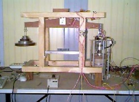
The whole prototype is based on the new 'RG Theory of Gravity Gravitation'. This is named after the Inventor Rakesh Goel. A series of prototypes have been made by him. I am also attaching a picture of the prototype [ titled as 'Gravity Motor' by us ].
On the right side is the Gravity Motor and on the left side are the counterbalancing weights. The heart of the Gravity Motor is the Capacito-Inductor which is also invented by Rakesh Goel. It is a 4 terminal device : 2 layers of metal and 2 of dielectric.
The electronics for the motor, current pulses etc. were not in good shape and after our breakthrough in May 2000 we have decided to have the electronic module as a single user friendly box. The work is on for this.
We propose to use 3 DSP processors for accurate measurements and motor control. Within 6 months the Gravity Motor and the Electronic module [ and Thesis ] will be available for Universities / potential clients so that they can purchase the set at a reasonable price and try it out at their end with their team and then tie up with us for the technology transfer / support.
Our proposed plan is as follow:
Phase 1 [ over by 2002 ] : 5 % weight change [ increase as well as decrease ] for Satellite positioning, orientation and accelerating vehicles in space.
Phase 2[ over by 2006 ] : 150 % thrust in vertical direction will be applied in fuel saving in vertical lifting of helicopters and space vehicles [ Space Transportation for Year 2015 ].
I can send you a thesis [ its not a very large document ] if you are interested to have a copy. Please tell me if you need one. This will tell you the design and construction and theory of the Gravity Motor and even the history of the inventor as to how the launch of Apollo 11 in 1969 sowed the seed in his mind re Gravity and the progress over the years.
With Regards
Deepak Jariwala - SK Dynamics

Updated 10/14/00
Design of Gravity Motor [Patent Pending]
The generation of Gravitational Force is based upon the new invented theory and the use of the newly invented electric component Capacito-Inductor which is a four terminal device and generates combined effect of capacitance and inductance. This is a novel technique which states that the applied voltage on Capacito-Inductor orients charge dipole in dielectric, impulse currents generate vibrations in charge dipole, rotation and superimposed vibration of Capacito-Inductor in presence of radial magnetic field generates axial gravitation field.
This design is suitable to generate the Gravitational Force at ambient temperature or even industrial / military temperature range without using any Superconductor. It employs a composite effect on charge dipoles in a dielectric material in presence of current impulses, rotation, vibration and radial magnetic field. As this prototype does not make use of any Superconductor, it can be easily used for space and avionics applications.
The gravity generation is controlled by the following control parameters:
1. Applied voltage – V
Function: To orient the charge dipoles inside dielectric
2. Current1 - I1 and Current2 - I2
Function: To vibrate the charge dipoles
3. Angular frequency - w
Function: To give velocity to the charge dipoles
4. Superimposed vibration amplitude - A
Function: To compensate the eccentricity of Capacito-Inductor rotation
5. Radial Magnetic Field Intensity - B
Function: To tilt the charge dipoles
6. Design parameters of Capacito-Inductor :
Dielectric Constant – K, Number of turns – N, Dielectric Thickness – d , Internal Diameter – ID, Outer Diameter - OD
It is a four terminal device A , B, C and D which offers inductance L between A to B and C to D. It also has sufficient capacitance between A to C or B to D. Its inductance is very small at A to C when B and D are shorted. It is used as the main component for generating Gravitational force.
It is a four-layer device with metal foil – dielectric film – metal foil – dielectric film, wounded on a cylindrical core as shown in Fig.8a. The first layer of the metal film is having its ends as the two terminals of the device i.e. A and B while the second layer of metal has its ends as other two terminals of the device i.e. C and D. These two metal layers have dielectric film layers in between as shown in Fig. 8b.
The apparatus consists of several components shown in Fig. 9 which are connected in the following fashion.
The magnetic rotor of permanent magnet synchronous motor (PMSM) rotates all the moving parts including Capacito-Inductor, PCB and slip-rings. The magnet creates radial magnetic field. Electronic PCB is also mounted on the rotating system and optically couples the two current pulse generators. The slip-ring assembly is mounted above the PMSM to feed power to electronic PCB. The whole system is supported with the help of the Top and bottom covers.
Role of each component of Fig. 10
a. First Power Supply to feed power to PCB for current pulse generator 2.
b. Second Power Supply to apply voltage V on Capacito-Inductor.
c. Third Power Supply to feed power to PCB for current pulse generator 1.
d. Slip-rings to transfer power to rotating PCB.
e. Current Pulse Generator 2 to generate current pulses I2.
f. Current Pulse Generator 1 to generate current pulses I1.
The Voltage is applied at the terminal A & C of the Capacito-Inductor through the power supply. Equal and opposite current pulses are applied at the terminals A-B and C-D of the Capacito-Inductor with the help of two Current pulse generators respectively. These two current pulse generators are opto-coupled to generate almost equal and opposite current pulses.
The second current pulse generator can be eliminated by short circuiting the terminals C & D. In this case due to high mutual inductance between the two coils A-B and C-D almost equal and opposite current is generated in both the coils with only one current pulse generator.
Description of the Gravity Motor:
The heart of the gravity motor is a four-layer device with metal – dielectric – metal – dielectric wounded on an insulating cylindrical core. It is a four terminal device A, B, C and D which offers inductance L between A to B and C to D. It also has sufficient capacitance between A to C or B to D. However its inductance is very small at A to C when B and D are shorted. It has been titled as Capacito-Inductor. It is placed between a magnetic circuit of permanent magnet which creates radial magnetic field.
When the Capacito-Inductor is rotated at high speed, voltage is applied between A and C, opposite current (dipole current) pulses are applied on A - B and C - D, it generates axial gravitational field. A PMSM used to rotate the Capacito-Inductor is operated with the help of a separate Electronic controller.
The applied voltage orients charge dipole inside dielectric in radial direction with negative and positive charge towards axis of rotation in alternate layers of dielectric. Rotation of Capacito-Inductor in presence of radial magnetic field tilts all the charge dipole towards negative charge down or up parallel to axis of rotation depending upon direction of rotation. Force vector on positive and negative charge is equal and opposite, therefore, the resultant effect is torque on charge dipole. The current dipole pulses generate vibration in charge dipole, and rotation of vibrating charge dipole generates gravitational force.
Download the .DOC file with more details
Other related information;
Electric Rocket Capacitive Warp drive
Another Electric Rocket site
Woodward - Mach's principle for capacitive acceleration
Aquino ELF Gravitational Experiment
Farrow Electrical weight reduction
Return to KeelyNet