The inertia of the roller will carry it past this null zone and into the magnetic
embrace of poles which now ATTRACT to PULL the roller the rest of the way
up the ramp.
 You will note in the construction details below that the magnetic side rails
must EXTEND BEYOND THE RAMP to allow the roller cylinder to drop out before
reaching the end. If you fail to do this, the roller will flip to one of
the sides due to the ATTRACTION of the UNLIKE POLES to each otherss.
This MAGNETIC GRADIENT applies to all magnets because there IS a null zone in
all of them. High 'pressure' on either pole that reduces as you approach the
Bloch Wall.
In the event of the TOMI, we have a magnetic roller that begins to
move under a PUSHING force across the weakening magnetic gradient to the null
zone, then inertia carries it into the PULLING zone, where its forward motion
continues until it drops off the end of the ramp.
You will note in the construction details below that the magnetic side rails
must EXTEND BEYOND THE RAMP to allow the roller cylinder to drop out before
reaching the end. If you fail to do this, the roller will flip to one of
the sides due to the ATTRACTION of the UNLIKE POLES to each otherss.
This MAGNETIC GRADIENT applies to all magnets because there IS a null zone in
all of them. High 'pressure' on either pole that reduces as you approach the
Bloch Wall.
In the event of the TOMI, we have a magnetic roller that begins to
move under a PUSHING force across the weakening magnetic gradient to the null
zone, then inertia carries it into the PULLING zone, where its forward motion
continues until it drops off the end of the ramp.
To construct your own TOMI (Theory Of Magnetic Instability) device;
1) For the ONE ramp test
Buy 30 circular magnets (with the hole in the middle) from
Radio Shack, these cost $1.69 for 5 magnets, so the magnets
will cost about $10.00
For the TWO ramp test
Buy 50 circular magnets (with the hole in the middle) from
Radio Shack, about $17.00
2) Take some stiff cardboard and make two hills (each hill
consists of an incline and a decline, experiment with the
angle, about 30 degrees)
3) Make three rolls (or five rolls if you are using 2 ramps) of
10 magnets each (connect the magnets to form 10 magnet stacks,
kind of like a roll of Lifesavers)
4) Tape these magnets together with scotch tape
5) The ones for the side of the ramps are called RUNNERS, one
other 10 magnet roll is used as the ROLLER that moves up the
incline perpendicularly between the RUNNERS
6) On each ramp (incline), you attach one roll of magnets running
up each side, so that's two magnet rolls per incline and NONE
on the decline
7) The RUNNER magnets on the sides should arranged to be of
opposite polarity, that is, North at the top on one side,
South at the top on the opposite side (it doesn't matter which
side is N or S, only that they are opposing)
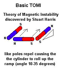
8) The ROLLER should be placed at the base of the ramp with its
poles facing like poles on the RUNNERS, since LIKE magnetic
poles REPEL, this will provide the repulsion you require to
make the ROLLER move up the incline between the RUNNERS.
For the Harris device, the 'over the hump' necessary for any perpetual motion device is provided by gravity on the roller as it moves down the decline. This effectively 're-loads' the machine for the next upward pass.
The inertia of the moving roller must be sufficient to get it past the attractive end of the guide magnets and over the apex of the incline/decline. This is something you will have to provide for in other configurations if you want to make it 'perpetual'.
To prevent attraction of the roller at the end of its travel, you should have the runner magnets extend beyond the incline, so that the runner drops down the decline and out of the attractive field of the end magnets.
One other tip, the more magnets you stack together, the weaker will be the overall force. A common idea is to create a circle of connected magnets that will provide a continuous acceleration.
It sounds good, but in fact will not work, so don't go out and buy $100s of bucks worth of magnets. Try it yourself by stacking 20 or so magnets
together and see how the field weakens.
The following diagrams show how simple it is to reproduce, experiment with it, have fun and we would all appreciate being informed of any improvements you might make.
 Make sure that the magnetic cylinders that are placed on the sloped sides of the
ramp, stick out BEYOND the ramp about an inch or so. This will let the roller
magnet DROP out of the embrace of the magnets. Once you see it work, you will
find you can make multiple ramps where the roller will roll up one, then drop
into the embrace of the next ramp and roll up to drop off that one...like
dominoes..its a neat effect. The hardest part will be to make sure the roller
is guided when it rolls up, the roller must be perpendicular to the two
side magnets that provide the driving flux.
Make sure that the magnetic cylinders that are placed on the sloped sides of the
ramp, stick out BEYOND the ramp about an inch or so. This will let the roller
magnet DROP out of the embrace of the magnets. Once you see it work, you will
find you can make multiple ramps where the roller will roll up one, then drop
into the embrace of the next ramp and roll up to drop off that one...like
dominoes..its a neat effect. The hardest part will be to make sure the roller
is guided when it rolls up, the roller must be perpendicular to the two
side magnets that provide the driving flux.
 RUNNER starts here
     \|/
      |   ----------------> direction of magnetic ROLLER
      |
      |       /             / (note: magnets extend beyond track)
      |     /\            /\
      |   /    \        /    \
      | /        \    /        \
      /            \/            \            magnetic
    |-------------------------------|  <----- S <--- _________ VIEW ENDS |<--ROLLER-- N TOP HERE MAGNET UP |_|_|_|_|_| ROLLER DIRECTION>| N      place roller between runners
                                    for repulsion
        ____________|____________
 |      |  S__|     |      |_N_  |
 |      | |___|  (start)   |___| |
 |      | |___|            |___| |        RUNNERS
 |      | |___|  incline   |___|<-- S MUCH AT INCLINE ___|____________|___ |________________________| SAME THE | MAGNETS OF ROLLS MAGNETS, |___|____________|___| (FINISH) |___| HERE, SLOPE |____________| ROLL N NOT DECLINE BETWEEN POSITIONED ANGLE <-------ROLLER HERE SPACE \|/ UP AS SHOWN <--NO BUT
The entire thing is difficult to get running, but when it is in
motion, it reminds you of a row of dominoes falling from a single
impulse.

