Hello All, It is time for this to be released. Build it for yourself and see the results. Permanent Magnet Motor (Non_Electric) - 04/14/01
Updates are appended as of 07/11/01 courtesy of Robert H. Calloway via Henry Curtis
Hello All, It is time for this to be released. Build it for yourself and see the results. Permanent Magnet Motor (Non_Electric) - 04/14/01
Updates are appended as of 07/11/01 courtesy of Robert H. Calloway via Henry Curtis
I have been appalled by the always present negativity that a PMM can’t, and will not work. It is said that the (2) forces, north @ south will always equal, no matter what you do. Other fairy tales are that the magnets would heat up if they were doing work. I am here to tell you that this is a bunch of cock and bull. Don’t believe these statements. This report is written to inform you that it can be done. Maybe after reading this you will reconsider on how to build a PPM. First, do some research. Please see: http://www.keelynet.com/gravity/curtis.htm Read this whole article, read everything associated with it, plus the patents. For a look at a PPM that I built and dared anyone to build, Please see it at the energy21 website titled: Hamster Cage Motor (the entire file is appended after this article). The Hamster cage motor is not considered by me a usable design, but it proves that it can be done. For a PPM that will do some work, we must consider the ideas of the Minato PPM. For a legitimate PPM, no electric coils or power must be considered. In the latter statements of the above url, he refers to using a coil or coils. Forget that. Build the motor to run on nothing but permanent magnets. Purchase a 36" wheel. Set this wheel up on bearings to freewheel easily. Purchase 50 Radio Shack part# 640_1877 magnets. They come 10 magnets to a bag, so 5 bags will do. Glue these magnets on the outside face side of the wheel, in a fashion shown on the url. The correct placement of these magnets will be when the wheel gates by a 5" long, by 2 1/2" wide, by 1/2" thick vertically curved magnet in the repulsive mode. The magnets will cover no more than 180 degrees of the wheel. When gluing magnets to the wheel, start at the outside of the face of the wheel and gradually work the magnets inwards so that the latter magnets in the 180 degrees wind up 3" inward outside of the wheel on the opposite side. FACT.. if you have done this properly the wheel will gate against the large magnet for 180 degrees. The magnets that you placed gradually in to 3" will not impair the wheel when it comes around to get back into the gate. The wheel will quickly build a speed of about 1200 RPM. My wheel is 1" plexiglas which is heavy. A lighter wheel will be faster. The wheel also needs to be balanced after proper placement of the magnets. Never consider a smaller wheel. Why? A smaller wheel with magnets attached causes closed flux loops with the main or primary magnet. When testing your wheel after the magnets are glued on, the wheel must gate freely through all magnets for 180 degrees then coast back around and back into the gate which starts the whole process over again. I like my motors ccw, but one can place the magnets to run either way. One can then gang rotors on a common shaft to produce power. With this much said, one should start by gluing the magnets all the way around the wheel 180 degrees without trying to work them inside 3". You will need practice on getting a perfect gate for the 180 degrees. A jig won’t do after 6 magnets are placed. You will encounter lockups and slow downs until all the magnets are placed correctly on the wheel. It takes much patience. With the magnets placed around the wheel along the outside, you will be able to gate out, but not be able to get back in. You can experiment with the gate by moving the large magnet out when the wheel comes back around to get in the gate. The wheel will keep turning and speed up quickly using this test method. When the wheel is setup correctly with the magnets moved in 3", the magnet can be placed in a permanet position by the wheel in a hands off situation. The wheel gates because of the relative size and angle of the wheel magnets versus the large size of the primary magnet. I suggest using "Quick Grab" glue wich is sold at Walgreens drug stores. It is a slow drying glue, but has a good instant bond in which a magnets position can be tested quickly. The magnet will pull off easily if in the wrong position, unless left overnight. Keep in mind that a magnet placed wrong early in the process can effect the gate later down the line on the wheel. NOTE! - CRITICAL TO ADJUSTING A MAGNETIC PMM - I have used metal filings in a plexiglass rectangled box just to view the various flux field effects as I placed magnets on the wheel. This PMM has a strong rotational push and a very strong kick leaving the 180 degrees of magnets. When ganging (2) rotors on one shaft, the rotors distance between them must be at least 30". The primary or main magnets must be placed on opposite sides of each rotor. But then..it is said that it cant be done... I have given you enough information to get busy. Regards, Robert H. Calloway
THE HAMSTER CAGE MAGNETIC MOTOR
If you take 2 rather large cylinder magnets and turn them so they oppose each other, one will roll away from the other. You can actually make the magnet go uphill with the other magnet without touching the second one. Keep in mind that the magnet is not trying to turn to escape the other magnet, it is only getting away from the other magnet by rotating because it is round Can we use this energy of the magnet rolling away from the other as work? I did it twice.
Ok the design works on the principle of a hamster cage effect.
Have you ever seen a hamster exercise in the wheel in his cage? As he tries to run up the wheel he goes nowhere, but the wheel goes around and around.
The rpm on mine was slow maybe 50 rpm. It turned about 16 turns before the top magnet hung up on the side plate. I have not been able to get it to work that long since.
The design is quite simple, but much patience is needed in the building and adjustment of the magnets for the motor to work properly.
As I said, adjustment of the magnets must be precise. Maybe one of you Engineers out there can perfect this design.
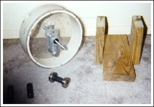
This motor consists of (4) 1x3 and 3/8 inch Alnico cylinder magnets.
Also (2) 1"id x 2"od stainless steel bearings.
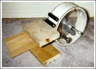
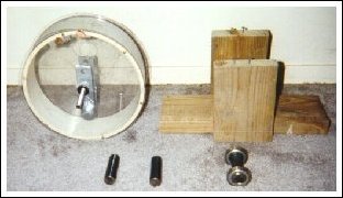
The cage is made of schedule 40, 10" id PVC pipe cut to 3 and 1/2 inches wide. The side plates are 1/8 inch plexiglass cut in a circle 11" across. The shaft is all thread 7/16 cut at a length of 10 inches.
The bearings for the shaft and plates are 1/2 id x 1 and 1/16 od inches, standard bearings.
A cradle must be made to hold (1) "chaser" magnet inside the wheel.
This cradle must be attached to the shaft to oppose the "running" magnet.
The reason for such large magnets are that each one has enough weight to keep from "flipping" when they are in the opposed position.
Plus the weight to wheel ratio on the motor is a serious consideration.
When the "chaser" magnet is in position in its cradle from the shaft,
the "running" magnet is opposed. It tries to go up the wheel away from the "chaser" magnet.
But this does not make the wheel turn, if fact the force on the "running" magnet is held against the wheel. It cannot turn.
We have to back off of the "chaser" magnet to give the bearings on the "running" magnet a chance to roll backwards, but the force of the "chaser" magnet is there, but not as strong.
When we put the same application on top of the wheel on the outside of it, we offset the balance of the magnets repulsion causing the wheel to turn, because the weight of the magnet offsets the centre "running" magnets repulsion from the "chaser" magnet.
The top "running" magnet starts to roll backwards causing the centre "running" magnet to roll forward causing the wheel to turn.
Be warned...the wheel must be in perfect balance, plus all these adjustments are critical.
It is not as easy as it seems! It takes much patience to get the adjustments correct to start the wheel turning.
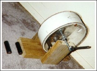
The plates will extend beyond the edge of the pipe, this is what it must do. We are building a hamster cage for the magnets.
Mount bearings in the centre of each plate and attach them to each side of the pvc pipe using brass screws. I used all thread material for the shaft.
Let me say here that it is of the most importance that the wheel be in perfect balance. I used pennies taped to the side of the wheel to obtain this.
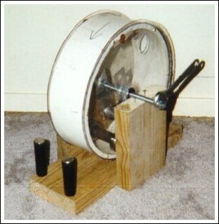
Now, build a bracket to hold one of the magnets inside the wheel attached to the shaft. I call this the "chaser" magnet. The chaser magnet must not contact the wheel anywhere.
Make your shaft a little long so as to adjust the chaser magnet from outside the wheel. I built mine out of aluminium carpet strips. It also helps to cut a 2" hole in each plate to access the magnets.
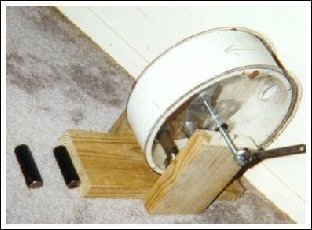
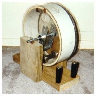
When the wheel it built, build a stand to hold the wheel supported by the shaft on each side. Purchase (2) stainless steel bearings1" id by 2" od.
Place one on each end of the "running" magnet. Be careful of your choice of bearings, some stainless steel bearings are attracted to magnets depending on the material they are made of. I suppose brass bearings would work if they can be found.
Place this "running" magnet inside the wheel through the 2" access holes in the plates in front of the chaser magnet.
If you have your chaser magnet and bracket built right, you should be able to move the running magnet back and forth by turning the shaft by hand outside the wheel.
Now, back the chaser magnet up away from the running magnet until the wheel starts to move in the opposite direction.
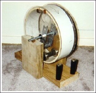
Keep it in this position for now. Take the other 2 magnets and place them on top of the wheel opposing one another. Note: these are a chasing and running magnets also.
Using the chasing magnet towards the bottom of the wheel gradually come down the side of the wheel holding the running magnet suspended against the wheel.
This is why the plate sides overhang the wheel to keep the magnets in line and to stay on the wheel.
Note: these magnets do not have bearings on them. I did wrap the running magnet with one turn of electrical tape to give it "traction" so to speak against the wheel.
When the wheel starts to turn, stop and build a adjustable bracket to hold the chaser magnet in this position. This is, as should be a "hands off" motor.
Build brackets and a adjustable stop for the shaft also.
Go back to the shaft and bring down the chaser magnet slowly and the wheel will turn if the adjustments are made correctly.
Adjustment of the bracket holding the magnet inside the wheel should be made adjustable.
All these adjustments are critical and takes much patience to do. But if you get them right, you will be humbled to watch it work.
Improvements:
I think if tracks could be made in the wheel hub, inside and out, that the magnets would stay in line more.
Perhaps the wheel could be made of a better material, such as aluminium. The magnets still have a tendency to "cock" without tracking.
Balance could be much better with a aluminium wheel. The distance between the shaft and the cradle to the wheel is critical.
The "chaser" magnet seems to have to have more down force on the "running" magnet as well as a repulsive force up the wheel.
But the repulsive force seems not as critical. I wish someone would consider replicating this design.
If this motor has a previous patent, I'm not aware of it. I give the design away as shareware.
Use it as you wish, but remember who offered this design! Send all huge donations to me personally.
Contact the Inventor Robert H. Calloway 
Update 07/11/01 - (still verifying this)
The following email was received by Robert Calloway and Henry Curtis, then forwarded to KeelyNet, we have asked for more details on the magnets, placement, RPM and possibly photos which will be appended as received. Hey guys, this is incredible. I was working on a design for a Perpetual Motion Device (PPM) based on magnets and I came across your site. My design was altogether different from yours, but I was searching on magnets and found your site. Well, since I had a workshop FULL of magnets, I decided to try and build a Permanent Magnet Motor for myself. I thought it would be difficult to get the magnets aligned correctly, but it was quite simple in fact. I spent about 30 minutes tops arranging the magnets. My design called for two thin sheets of Plexiglas cut into 36 inch circles. I mounted bearings to each, and mounted them on an axle. I took two curved sheets of Velcro, and attached them to half of each wheel. I glued the other side of the Velcro to the sides of each magnet. This would allow for easy repositioning of the magnets. I then sandwiched the magnets between the sheets of Plexiglas, to add to the Velcro's strength in holding them in place. I weighed the magnets, and added weights of equal weight to the other side of the wheel, to balance it. After a few lockups and magnet repositioning, it did start to spin and spin strongly! It's pretty impressive. Anyway, I then bought a simple 6-volt light generator for a bike at Wal-Mart and started to power all sorts of things. I want to find a small 12-volt generator, so I can power practical 12-volt items which are widely available. I'm hoping, quite soon, to be able to power most electrical items in my house from generators running off these things. This invention is HUGE! How come you guys are not more popular? John
Update from Robert Calloway on 07/11/01 Magnets...leave the thought of north and south behind for now. Think flux, repelling flux against another repelling magnet. Flux can be manipulated. Flux is the wind. The flux fields between two repelling magnets does no join or intermingle. They bulge and deform into different shapes and patterns. Building a PPM requires looking at these flux patterns. All magnets are never the same, even though they look and feel the same. One could build a PPM and then copy it exactly, and it would not work. You MUST see the flux pattern. I have specifically said you must view these patterns using a box with metal filings. If you build a PPM without doing this, you are very lucky. "John T" has said that he has built the PPM, and I hope that he has done so. He has also said that he has turned a 6 volt generator with it, and I hope that he has done so. "John T" must explain how he turned the generator with the bearings installed to the disks? That means there is no shaft to turn to drive the generator. He could conceivably turn the generator from the disks I suppose. I truly hope he did. I am beholding to an agreement against full disclosure on this design. Regards, Robert H. Calloway Magnetic Anomalies