Zapper Schematics
No claims are made by KeelyNet for any of these plans
They are provided for informational purposes only!
KeelyNet 01/10/02
Simple Zapper Schematic
The Research of Dr. Hulda Regehr Clark, Ph. D., N.D. I have recently (9/15/2000) come across the research of Dr. Hulda Regehr Clark, Ph. D., N.D. In her books, she states that many diseases, among which are cancer and HIV/AIDS, can be cured by the use of, among other things, certain herbs and a frequency generator called a "Zapper" that was invented by her and her son. Speaking of mothers :), my mother, 62, had fatigue and arthritic symptoms in her hands before I found out about and told her about Dr. Hulda Clark. She is a seamstress, so the arthritic symptoms hindered her work. After doing the Parasite Cleanses and using the Zapper, she doesn't have to take naps like before and her hands are flexible again. She has done the complete Parasite Cleanse only twice but she Zaps practically every day. Simple Zapper Information
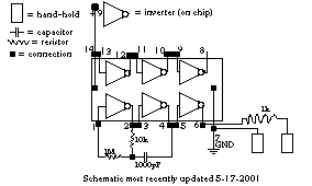
Schematic updated on 12/21/2001
Simple Zapper Information text updated on 12/21/2001. I forgot to mention that the Simple Zapper that I'm using has a 1 Megohm potentiometer instead of the 2.2k ohm resistor in order to vary the output frequency. If you use a potentiometer with the circuit put it in series with the 2.2k ohm resistor because the chip gets hot when there is too little resistance. The duty-cycle is pretty consistent with a range of 51% to 57%. With the oscilloscope's frequency analyzer in storage mode, I hold the Zapper probes and put the oscilloscope probes somewhere on my body and then I vary the frequency of the Zapper using the 1 Megohm potentiometer. When testing my body on a spectrum analyzer while using the Simple Zapper with an output of around 5 Volts (tested on a DC voltmeter), I noticed that the frequencies around 4,000 hz to around 18,000 hz had larger peaks telling me that my body at the time was more conductive (less reactive?) and/or less resistive to frequencies in this range at the given voltage. With my body being more conductive (less reactive?) at these frequencies, I believe that there is a better dispersal of the Simple Zapper's output within my body. I did this recent test with one Zapper probe in each hand (as opposed to both in one hand) and the oscilloscope probes (RCA to 1/4" phone plug adaptor) in my mouth near my wisdom teeth with my lips around the RCA ground (like a lollipop). The oscilloscope's frequency analyzer was in storage mode. With the Simple Zapper circuit on this page, change the 2.2k ohm resistor to 4.3k ohm if you want a ~15,000 hz frequency. I have recently built a couple of Zappers with optimized output frequencies of around 11,000 hz. I haven't tested anyone using the Simple Zapper other than myself, so there is the possibility that your body's response may differ. For more information, check out my Simple Zapper webpage at: www.members.aol.com/mas1911/index.html or for really interesting free circuit schematics: www.members.tripod.com/~mas1911/zappers20011221tripod.html You can write the Author of Simple Zapper if you have comments or questions.The following document, written by Luke Parrish, provides instructions on building an astable multivibrator in DC pulse mode, identical in output to the Zapper, described in The Cure For All Diseases by Dr. Hulda Clark. This page tells how to make a Hulda Clark-style "Parasite Zapper". It's a simpler and more efficient version, but works just as well. We make no theraputic claims for this device. It is for experimental purposes only. We provide a ready made version for those who prefer not to spend so much time building it. Plans For Zapper
Materials
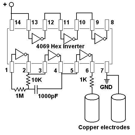
- A CD4069 hex inverter (Radio Shack link)
NOTE: The size of the resistors and capacitors can vary, because they determine the frequency of the zapper, which doesn't really matter much according to Hulda Clark.
- 1 1M resistor, 1 10k resistor, and 1 1k resistor (Radio Shack link) (Resistor color code)
- 1 1000 pF capacitor (Radio Shack link)
The following parts may be substituted according to preference, though something similar will be needed:
- Solderless breadboard (Radio Shack link)
- 9-volt battery
- 4 alligator clip-leads sets Radio Shack link
- 2 copper pipes (hand-holds)
Instructions
Plug the components into the solderless breadboard according to the following schematic. Make sure none of the wires touch each other. To hook up the power, attach an alligator clip-lead to each side of the capacitor that stretches from hot to ground. Clip the one that goes to hot to the positive terminal on the battery and the one that goes to ground to the negative terminal. The two hand-holds are attached with the other two clip-leads. (One goes to ground, the other to the end of a resistor that goes to pin 12.)
Schematic
The above instructions are not the only way to do it. You can, for example, solder all the components directly to a 14-pin socket, like we do in our ready made version. This is a lot more trouble and more time-consuming for most people, which is why we recommend a breadboard. The resistors and capacitor don't all have to be the exact sizes mentioned here to make a working Zapper. However, any variation in capacitance or resistivity will change the frequency. (There are certain limits on how high of frequencies the chip can handle, so don't stray too far from the specified values.) If you have an oscilliscope, that's handy to check if it's working.
Ready made ZappersFree plans from Zapperlab.com Here we have the easy step-by-step instructions for building your very own Hulda Clark Zapper reprinted with permission from her books (provided below). For advanced electricians there is a schematic for building a Hulda Clark Zapper as well. If you do not know anyone that could put one together for you, you can now order the zapper Hulda Clark uses as described in "The Cure For All Cancers" and "The Cure For All Diseases" at: www.SyncroZap.com. The Dr. Clark Zapper can be sold only as an experimental device, and no claim can be made by us legally as to a diagnosis, cure or treatment for any medical condition or disease.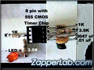
Build A Dr. Clark Zapper
Instructions for building your very own zapper can be found reprinted below from the books by Dr. Hulda Clark. If you would rather order a pre-built zapper, just click here.
How To Build A Zapper from The Cure For All Cancers:
The Cure For All Cancers � Copyright 1993 by Hulda Regehr Clark, Ph.D., N.D.Get from Radio Shack, (serial number included to make it easy).
Order these parts from their web site at: www.RadioShack.com___ Black plastic Project Box Radio Shack # 270-1809
___ 9 volt battery
___ 9 volt battery clips: Radio Shack # 270-325
___ On off switch: Radio Shack # 275-624A
___ 1K Ohm resistor: RS# 271-1321
___ 3.9K Ohm resistor: RS# 271-1123
___ low current red LED: RS# 276-044
___ .0047 uF capacitor: RS# 272-130
___ .01 uF capacitor: RS# 272-1065
___ 555 CMOS timer chip: RS# 276-1723
___ 8 pin wire wrapping socket for CMOS chip: RS# 276-1988
___ two packs of Microclip test jumpers: RS# 278-017
___ one pack of 14" alligator clip leads RS# 278-1156C
Get from any Hardware Store:
2 Bolts 1/8" diameter, 2" long with 4 nuts and washers.
2 pieces of �" copper pipe, cut to 4 inches long each.
Editor's Note:
The 8 pin wire-wrapping socket has been discontinued at many Radio Shacks and readers have asked what to do. Some say it is still available on their website at www.RadioShack.com, if not:
There are a couple options. One can still get the 16 pin wire-wrapping socket. Pull out the bottom grouping of 8 pins, and you now have an 8 pin socket. Just make sure when you plug the 555 Timer into it, you line it up with the remaining 8 pins. Very simple.
There is also a Low Profile 8 pin socket. The pins are so small one must solder to them.
The wire-wrap socket has long pins for easy twisting onto other wires. The low profile is for those that solder electronics.
If you are soldering your zapper together get the low profile 8 pin socket. Since the socket is just a saddle for the 555 Timer, it is not a vital part of the circuit. It's just a way to put long or short pins on the 555 Timer for easy twisting. If you cannot find one at your local Radio Shack, simply get the 16 pin wire-wrap socket, and pull out 8 pins. -editor.
Assembling The Zapper
If you have tools such as a drill, needle nose pliers, and small drill bits, buy one of the plastic project boxes on the list, otherwise build your zapper in a shoe box, or a box half the size of a shoe box.
1. You will be using the lid of the shoe box or plastic lid of the project box to mount the components. Save the box to enclose the finished project.
2. Pierce two holes near the ends of the lid. Enlarge the holes with a pen or pencil until the bolts would fit through. Mount the bolts on the outside about half way through the holes so there is a washer and nut holding it in place on both sides. Tighten. Label one hole "grounding bolt" on the inside and outside.
3. Mount the 555 chip in the wire wrap socket. Find the "top end" of the chip by searching the outside surface carefully for a cookie-shaped bite or hole taken out of it. Align the chip with the socket and very gently squeeze the pins of the chip into the socket until they click in place.
4. Make 8 pinholes to fit the wire wrap socket. Enlarge them slightly with a sharp pencil. Mount it on the outside. Write in the numbers of the pins (connections) on both the outside and inside, starting with number one to the left of the "cookie bite" as seen from outside. After number 4, cross over to number 5 and continue. Number 8 will be across from number 1. The pins are numbered like this:
1
8
2
7
3
6
4
5
5. Pierce two holes � inch apart very near to pins 5,6,7, and 8. They should be less than 1/8 inch away. (Or, one end of each component can share a hole with the 555 chip.) Mount the .01 uF capacitor near pin 5 on the outside. On the inside connect pin 5 to one end of this capacitor by simply twisting them together. Loop the capacitor wire around the pin first; then twist with the long-nose pliers until you have made a tight connection. Bend the other wire from the capacitor flat against the inside of the shoe box lid. Label it .01 on the outside and inside. Mount the .0047 uF capacitor near pin 6. On the inside twist the capacitor wire around the pin. Flatten the wire from the other end and label it .0047. Mount the 3.9 K Ohm resistor near pin 7, connecting it on the inside to the pin. Flatten the wire on the other end and label it 3.9. Mount the 1 K Ohm resistor and connect it similarly to pin 8 and label it 1K.
6. Pierce two holes � inch apart next to pin 3 (again, you can share the hole for pin 3 if you wish), in the direction of the bolt. Mount the other 1 K Ohm resistor and label inside and outside. Twist the connections together and flatten the remaining wire. This resistor protects the circuit if you should accidentally short the terminals. Mount the 3.9 K Ohm resistor downward. One end can go in the same hole as the 1K resistor near pin 3. Twist that end around pin 3 which already has the 1K resistor attached to it. Flatten the far end. Label.
7. Next to the 3.9 K Ohm resistor pierce two holes � inch apart for the LED. Notice that the LED has a positive and a negative connection. The longer wire is the positive (anode). Mount the LED on the outside and bend back the wires, labeling them + and - on the inside.
8. Near the top pierce a hole for the toggle switch. Enlarge it until the shaft fits through from the inside. Remove nut and washer from switch before mounting. You may need to trim away some paper with a serrated knife before replacing washer and nut on the outside. Tighten.
9. Next to the switch pierce two holes for the wires from the battery holder and poke them through. Attach the battery and tape it to the outside.
Now To Connect Everything
Twist free ends of the two capacitors .01 and .0047 together. Connect to Grounding Bolt using an alligator clip.
Bend pin 2 and pin 6 together inward, using an alligator clip, catch them and connect to free end of 3.9K Ohm (by pin 7).
Alligator clip Pin 7 to free end 1K Ohm (near pin 8)
Using two microclips Pin 8 and pin 4 to one end of switch (use hole to attach both microclips).
Free end of 1K Ohm (by pin 3) to the Bolt using an alligator clip.
Alligator clip the free end of 3.9K Ohm (by pin 3) to plus end (long) of LED.
Minus end (short) of LED to Grounding Bolt with an alligator clip.
Alligator clip pin 1 to the Grounding Bolt.
Alligator clip Black battery wire to Grounding Bolt.
Micro clip the Red battery wire to free end of switch.
Hook up the battery, and the light should turn on, click the switch if it does not, check connections if LED does not light up.

Attach a long lead wire to the grounding bolt & bolt, and then to the copper handles. Wrap handles in paper towel, clip with lead wire, wet handle when you are ready to zap.)
How To Zap
Wrap handles in wet paper towel, or wet cotton sleeves, and hold in each hand. If you have wrist cuffs, run them under water to wet them, attach to each wrist.
Attach handles or wrist cuffs to zapper.
Turn zapper on, zapping for 7 minutes.
At end of 7 minute zapping rest 20 minutes.
Do this a minimum of three 7 minute zapping sessions, with a 20 minute break in between each session. Some people zap five times in extreme cases.
Order A Dr. Hulda Clark Zapper - Click Here!
Learn about Dr Clark's latest zapping technique at: www.PlateZapping.com
All information is for educational purposes only. These statements have not been evaluated by the FDA. Not intended to diagnose, treat, prevent, mitigate or cure disease.
This Circuit designed by Geoff Clark and approved by Dr. Hulda Clark
If you found this file useful or interesting, please consider a donation or a purchase to help keep KeelyNet online and providing free information. Even a dollar will help. Others sell it, we prefer to share it, thanks! |